Mini-pat electronic systems and control
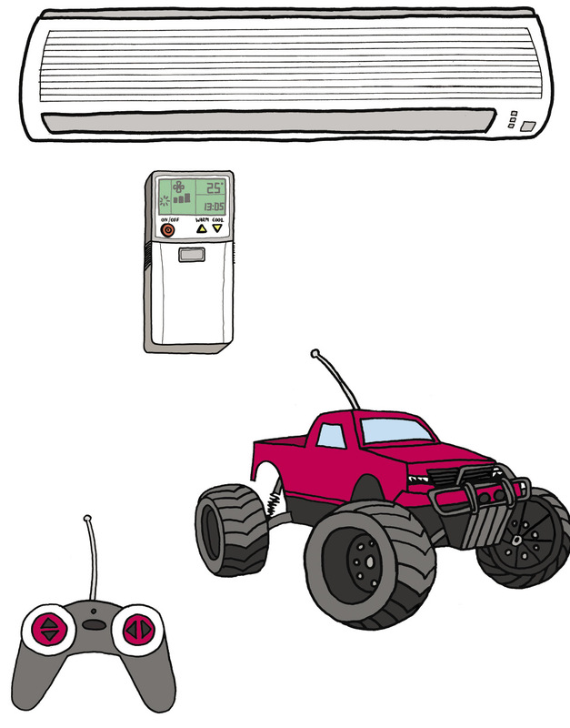
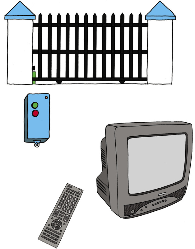
Figure 1: Many everyday devices use electronic control circuits.
An electronic circuit is different from an electric circuit because it only uses a very small current, and because it uses electronic control devices such as thermistors, LDRs, diodes and transistors.
Ordinary circuit breakers:
Shuts off a circuit (for example the circuit supplying all the lights in a house) when the current becomes too big (if the current is too big for the thickness of wire used, the wire will overheat).Residual-current circuit breakers:
Switches off the main power supply if it detects a leakage of power, such as when a person accidentally touches a "live" electrical wire or contact and the electricity is then conducted through his or her body. This device has to cut the current very quickly; otherwise the person can die due to electric shock. Therefore it switches off the power even when it detects only a small amount of leakage of electrical current.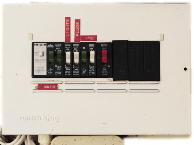
Figure 2: An electrical distribution board with circuit breakers
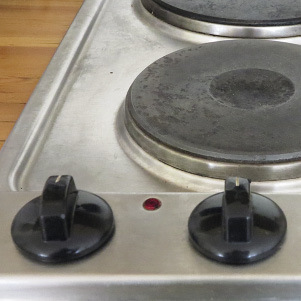
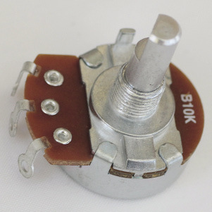
Figure 3: The control knob of a stove plate is connected to a variable resistor. This controls the current through the heating element. The bigger the current, the hotter the plate will be.
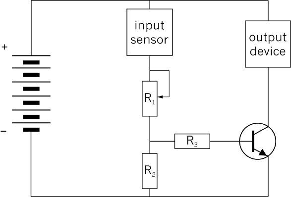
Figure 4: The control circuit that you built in Chapter 5 for a fire alarm
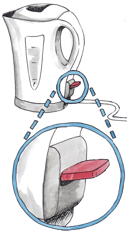
Figure 5
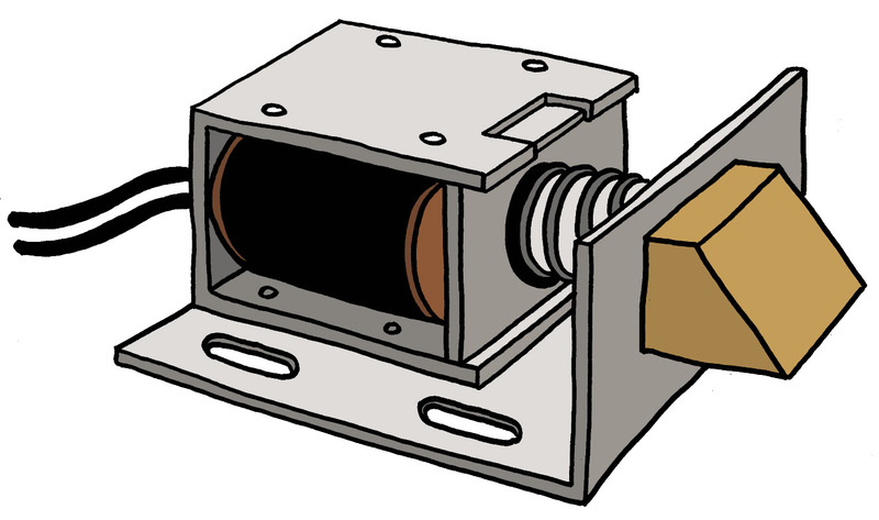
Figure 6: An electric door lock
Figure 7: A 3D assembly drawing of the parts inside an electric door lock
 Week 2
There is no such thing as a perfect design! For example, you can make a complicated design that will work very well, but that will be expensive and difficult to build. Or you can make a simple and cheap design that works, but is not strong enough.
Learn from the different designs that different people madeIf someone makes a negative remark at this stage, you should say "Red flag! No negative remarks at this stage."
Saying "Mary's made a bad design" or "Sipho's is much better", for example, will hurt someone's feelings or make others feel proud or arrogant. If someone says "Mary's design ...", you should say "Red flag! We call that Design C."
If you do not do this, you
won't be able to build a model of your design.prototype.Designers and engineers usually make many prototypes before the design is good enough to start manufacturing and selling it. Each prototype is an attempt to improve on the previous one.
An alternative to the kettle swicth project: Designing and building a circuit continuity tester
Your teacher may decide to let you do the following project instead of designing and building an automatic kettle switch.
Often when people have to connect wiresin electric circuits, there are so manywires that it is difficult to know whichtwo wire ends are of the same wire.
It would help to have a device thatshows whether two wire ends areconnected or not. This is whata "circuit continuity tester" does.
Figure 8
A circuit continuity tester is actually an open circuit. The circuit can only be closed by the two wire ends thatyou are testing. Use the two test leads of the circuitcontinuity tester to touch the two wire ends that youwant to test. If there is a path for current to beconducted between the two wire ends, this willcomplete the circuit and a light or a buzzer on thecircuit continuity tester will be activated.
Safety warning:
First switch off the power supply before you do a test such as this one.
Note that a circuit continuity tester cannot tell you whether the two wire ends are of the same wire. It can only tell you whether there is a path for current to be conducted between the two wire ends, in other words whether the two wire ends are electrically connected. But if you know that there are no splitting or joining of wires in between the two wire ends, then the wire ends can only be electrically connected if they are of the same wire.
If you design and build a circuit continuity tester as your project, think about the following:
- It should be easy to let the test leads of the circuit continuity tester make proper electrical contact with the wire ends.
- The tester should be small.
- The tester should be protected from shocks, for example if it gets dropped.
- The tester should be protected from water, since water can cause a short circuit.
A few ideas for building a circuit continuity tester are shown in the photos below.
Figure 9
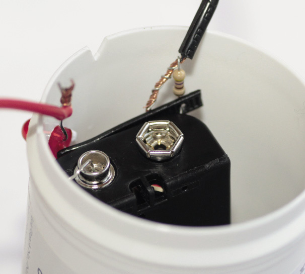
Figure 10