Build and draw electronic circuits
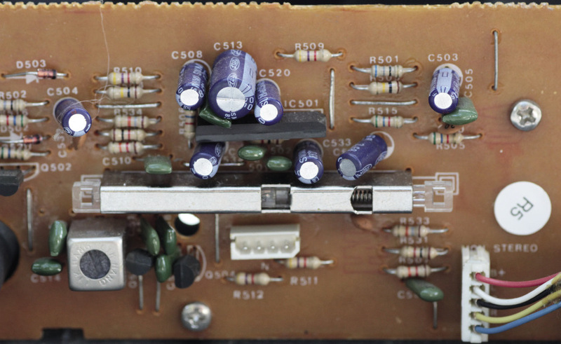
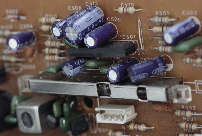
Figure 1: A part of the circuit for a radio
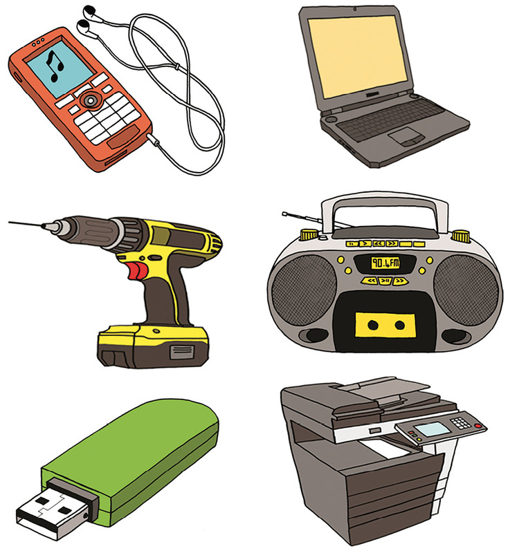
Figure 2: All of these appliances contain electric circuits.
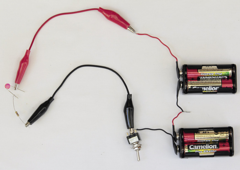

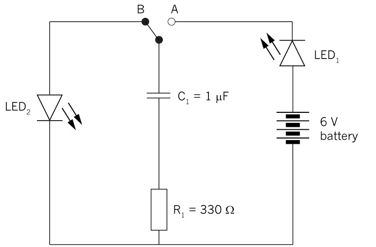
Figure 3: A circuit with an LED, a battery, a switch and a resistor
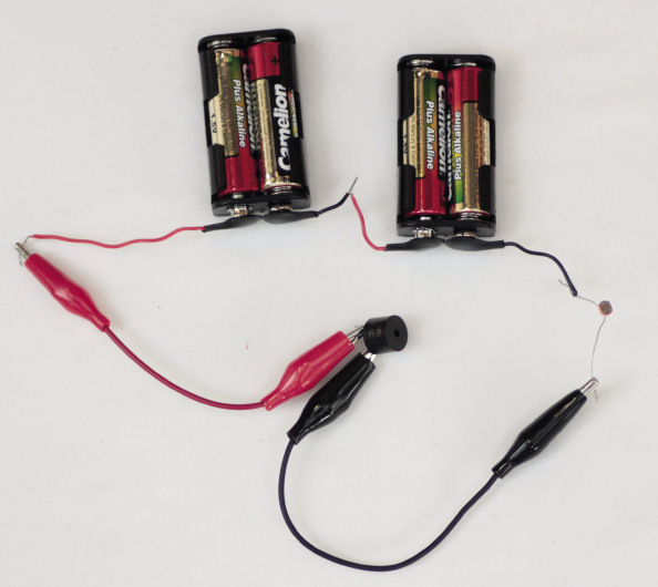
Figure 4: A circuit where the current is regulated by a light-dependent resistor
output device on and off without
using a switch. Instead of a switch controlled by hand, this
type of circuit uses an input sensor in combination with
a transistor to switch the output device on or off automatically, depending on the
measurement of something by the input sensor.control circuit since one
circuit controls another circuit. In the case where a
transistor is used with a sensor such as an LDR, the
base-emitter current controls the larger collector-emitter
current.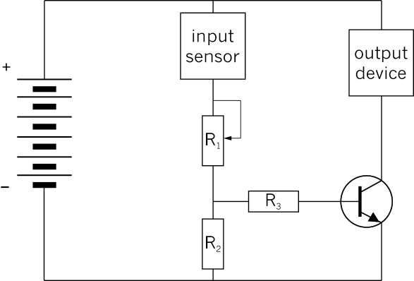
Figure 5: The circuit diagram for the control circuit
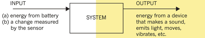
Figure 6: A systems diagram of a control circuit
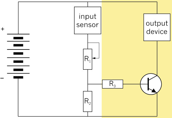
Figure 7
Figure 8: A circuit diagram showing the different components in a fire alarm

If you try to build a more complicated circuit by connecting components using conducting wire and crocodile clips, many wires will cross one another and the circuit will be messy, looking like a tangled bunch of ropes.
To make a complicated circuit in a neater and smaller way, most circuits are built on boards such as "bread boards", "strip boards", or "printed circuit boards" (PCBs).
Figure 10 below shows a simple LED circuit, such as the one you built in section 5.1, but here it is built on a strip board. Notice that there are no connecting wires used to build this circuit! This is because at the bottom of the strip board there are parallel copper strips connecting the holes in each column. This makes it possible to construct a circuit without using wire.
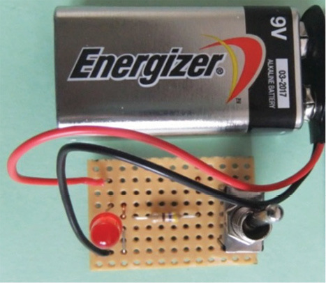
Figure 10: A simple LED circuit built on a strip board
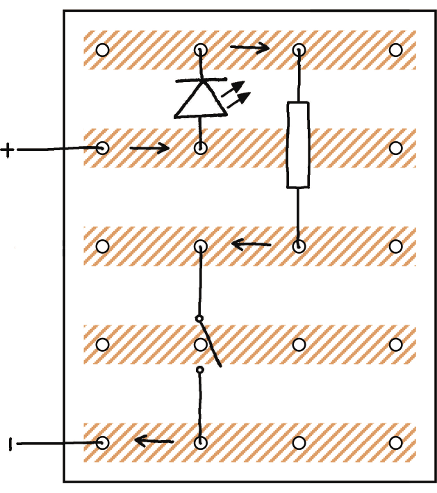
Figure 11: One possible layout of the simple LED circuit on a strip board
Figure 11 shows one possible plan of how to arrange the simple LED circuit on a strip board. The copper strips are at the bottom of a strip board, and not visible from the top. Therefore the copper strips on the drawing of the layout were drawn with hatching, to show that you cannot really see them from the top.
The arrows on Figure 11 are drawn to help you understand how current flows through the copper strips at the back of the strip board. The current flows in the direction of the arrows.
The connectors of the components are soldered to the copper strips at the bottom of the strip board. This is to ensure that they make proper electrical contact with the copper strips.
Soldering is done with lead, because lead is a good electrical conductor and has a low melting point, so it is easy and quick to melt it with a soldering iron.
Bread boards and printed circuit boards are other types of boards used to build complicated circuits. They also have copper connections at the back, but these connections are arranged in a different way than on a strip board.
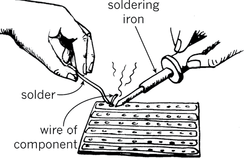
Figure 12: Soldering components onto the back of a strip board
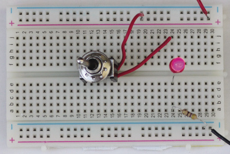
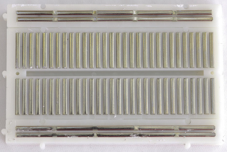
Figure 13: The front and back of a bread board
With a breadboard it is not necessary to solder connections, since each hole in the breadboard has a spring that grips the wire tightly to make proper electrical contact.
Almost all manufactured electronic devices use printed circuit boards, where the copper connections at the back can be made in any pattern. This makes it possible to make complicated circuits that are very small.
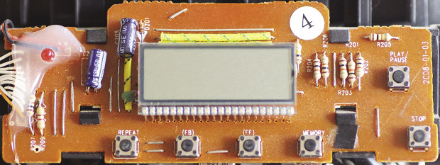
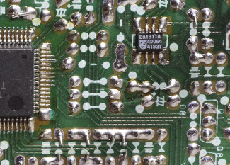
Figure 14: The front and back of a printed circuit board