Electronic components 1
In this chapter, you will learn about electronic systems and about components in electronic circuits. You will also learn about the following control devices: switches, diodes and transistors. Finally, you will make a simple transistor circuit. An electric circuit consists of an energy source and conductors. Conductors connect components such as input, output and process devices to create a path for the electrons to flow to and from the source of energy. Insulators are used to keep the components from short-circuiting.
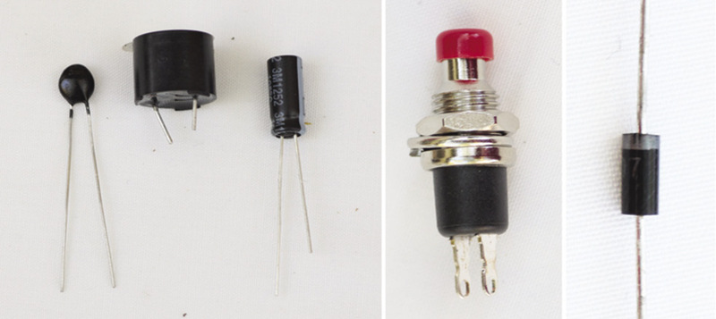
Figure 1: A few examples of electronic components that we will deal with in this chapter
Switches
A switch controls the electric current by closing or opening the circuit. There are various types of switches that control the circuit in different ways. In this lesson, you will learn about manual switches that a user can turn on or off.
1. Think about different switches that you use daily and list them here:
Push button switch
Push button switches are often used for doorbell circuits, as in Figure 2. This simple doorbell circuit consists of cells in series, a push button and a buzzer, all connected by conducting wire. A person visiting the house presses the button for a short time and then releases it.
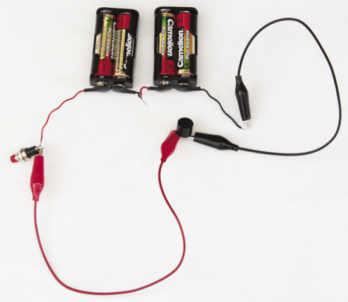
Figure 2: A simple doorbell circuit
2. Draw the circuit diagram of the doorbell circuit in the photograph. Use the correct circuit diagram symbols. Note that the cells are in series.
 Single-pole,
single-throw switch (SPST)
Single-pole,
single-throw switch (SPST)
Figure 3: The symbol for an SPST switch
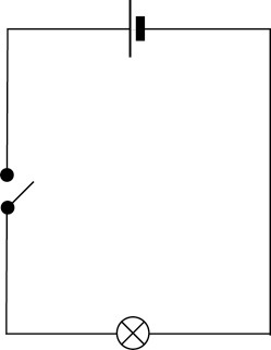
Figure 4: A typical light circuit with anenergy source, switch and lamp
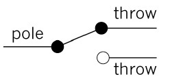
Figure 5: The symbol for an SPDT switch
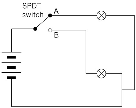
Figure 6: A circuit with a battery, two lamps and an SPDT switch controlling two outputs
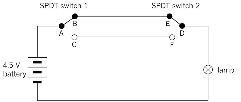
Figure 7: A circuit with two SPDT switches is often used to control a lamp with one switch at each end of a long passage. It is also used to control a lamp with one switch at the bottom of a staircase, and the other switch at the top of the staircase.
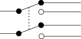
Figure 8
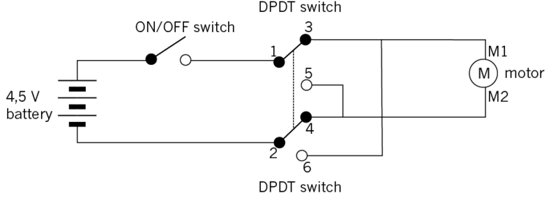
Figure 9: A circuit where a DPDT switch controls the direction in which an electric motor turns
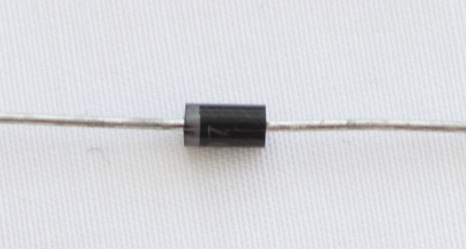
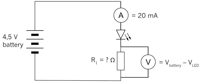
Figure 10: A diode
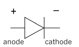
Figure 11: Circuit symbol of a diode. The current flow in a diode is in the direction of the arrow head.
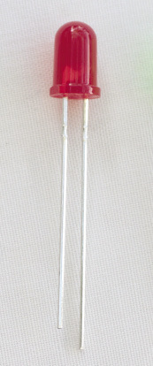
Figure 12: An LED. The longer of the two wires coming out of the LED should be connected to the positive terminal, and the shorter wire to the negative terminal.
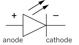
Figure 13: The circuit symbol for an LED.
 collector, base and emitter.
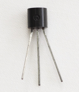
Figure 15: One type of transistor
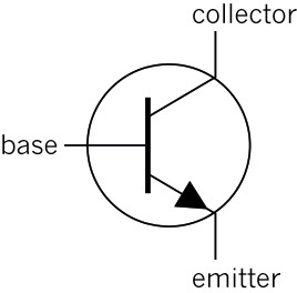
Figure 16: The circuit symbol for an npn transistor
There are other types of transistors, for example pnp transistors that work a bit differently from npn transistors. But you will only work with npn transistors in this term.
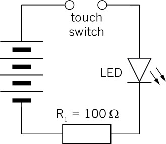
Figure 17: A simple touch-switch circuit that will not work well
A transistor uses a small current circuit to switch on a larger current circuit. This is why transistors are also used in music equipment to "amplify" the sound.
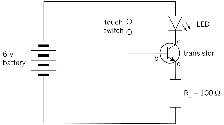
Figure 18: Circuit using a transistor as an electronic switch
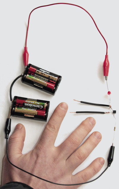
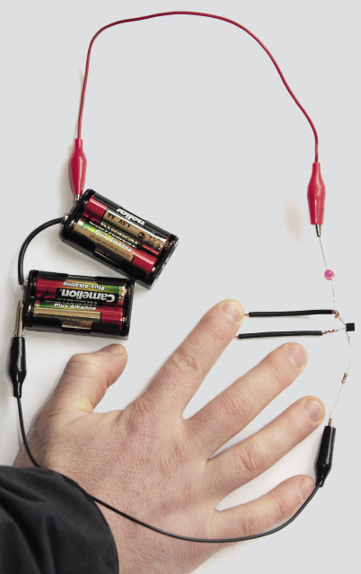
Figure 19: The construction of a touch-switch circuit with a transistor and an LED.