Circuits with logic control
In this chapter, which brings you to the end of this term, you will start by revising the circuits you made in Chapter 7 at the beginning of this term. Then you are going to use this knowledge to make an alarm system for a shopkeeper.
You will only do individual work during this Mini-PAT.
Week 1
Circuit diagrams and ohm's law
This section revises the circuits which you learnt about in Chapter 7. You found that the more cells you connected in series, the brighter the bulb glowed.
Revise the effect of connecting more cells in series (45 minutes)
You will need:
- a cell holder big enough for three cells,
- two or three crocodile-clip conducting wires, and
- a light bulb rated for 3,8 V or slightly more.
Look at the three circuits below:
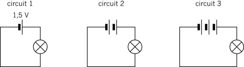
1. What voltage does the battery in circuit 3 promise to give?
2. Predict how bright the bulbs will glow in circuits 1 to 3. To show your prediction, draw brackets around the bulbs in the diagram. (⊗) means dim, ((⊗)) means medium bright and (((⊗))) means very bright.
3. Now build each of these circuits and test your predictions. Does the bulb in each circuit glow as brightly as you predicted it would?
The relationship between voltage and current
If the current through the bulb is small, the bulb will glow dimly, and if the current is big, the bulb will glow brightly.
4. Write a sentence about the relationship between the voltage and the current. Use the following phrases in your sentence:
- "across the bulb",
- "through the bulb",
- "the voltage is",
- "the bigger is the current", and
- "the bigger".
5. You can state the relationship between current and voltage in another way. Complete the following sentence:If you increase the __________ across the bulb, you also increase the __________ the bulb.
The sentence above summarises Ohmâs law.
Revise circuits with resistors in series and parallel (45 minutes)
For this activity, you will need:
- a battery of three cells,
- three bulbs rated for 3,8 volts, and
- six crocodile-clip conducting wires.
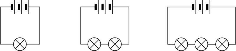
1. The diagrams in Figure 3 show you the circuits you are going to build. Before you build them, show your predictions of how bright the bulbs will glow on the diagrams using brackets as you did before. Then connect the components and test your predictions.
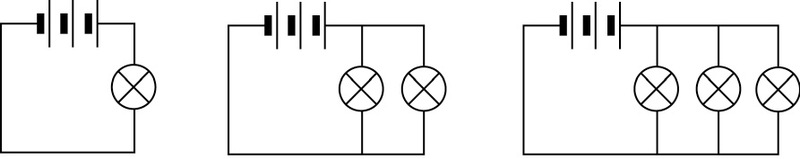
2. Look at Figure 4, and show your predictions of how bright the bulbs will glow when they are connected in parallel. Then connect the components and test your predictions.
How a door-operated push switch works (30 minutes)
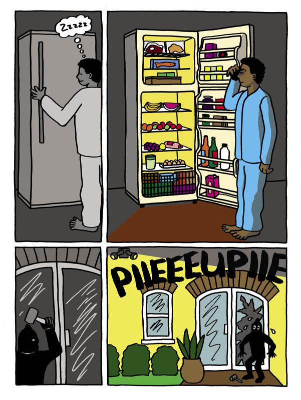
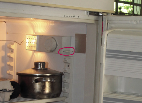
A refrigerator has a light bulb inside that lights up when you open the door.
1. Will the light turn off when you close the fridge door? Why?
2. Figure 5 shows a photo of a fridge with its door open. On this photo, find the switch that controls the light and draw a circle around it with your pencil.
3. Homework: When you open a fridge at home, press this button in to see whether the light goes off.
- Many push switches turn on a circuit when they are pressed in, and turn off the circuit when they are is not pressed in.
- But the push switch for the fridge light works the other way round. It turns off the circuit when it is pressed in, and it turns on the circuit when it is not pressed in.
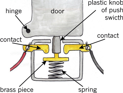
Figure 6 shows you how this type of switch works. The switch opens the circuit as long as the door is closed.
4. What happens when the door moves away from the plastic knob? How does the switch complete the circuit?
Week 2
Logic gates and truth tables
Design brief and specifications
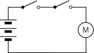
Switches with and-type control (15 minutes)
The circuit in Figure 7 has AND-type control. Now let's see where people would use a circuit such as this one. Figure 8 shows an electric paper-cutting machine that is used to cut many sheets of paper simultaneously. An electric motor turns gears that press the blade of the machine down to cut the paper.
A worker who uses the machine could easily cut his or her fingers, so the machine has a safety system in place.
To make the blade come down, the worker must use both hands to press two switches at the same time. If he or she presses only one switch, the blade will not move. So the machine will not work unless his or her hands are both out of the way.
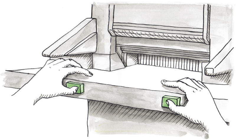
This machineâs circuit has AND-type control. Switch 1 and Switch 2 must both be closed, by pressing them, before the motor will work.
Switches with or-type control (15 minutes)
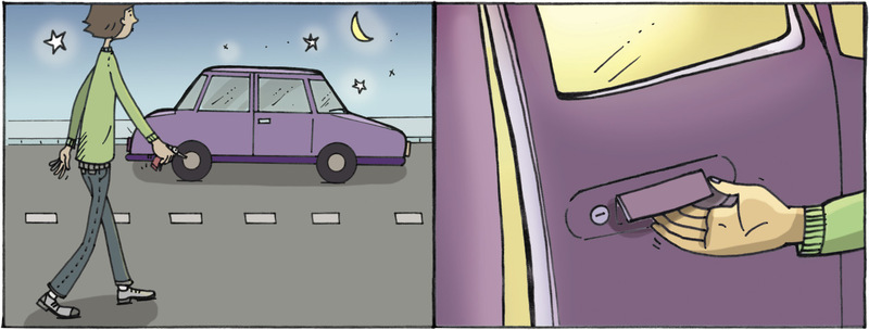
The circuit in Figure 9 has OR-type control. This type of control is used to switch on the light inside a car when you open one of the front doors. This is very useful when you get in or out of the car at night.
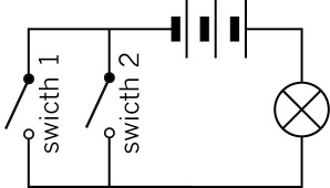
The light turns on when the driver opens the door, and turns off when that door is closed. If a passenger gets in at the other front door, the light goes on again, even if the driver's door is closed.
So the car has a circuit that switches on the light if either the driver's door is open or the passenger's door is open. This circuit has OR-type control.
A carâs cabin light uses OR-type control because the bulb lights up if either the switch on the driverâs door or the switch on the passengerâs door is closed (on). It also lights up if they are both closed (on).
1. Look at the circuit in Figure 9. Both the switches are open (off). How can you get the bulb to light up? Think of three things you can do with the switches.
The door-operated switch for the light inside the car is the same type of switch used for a fridge light, as shown in Figures 5 and 6.
Truth tables (30 minutes)
A computer gives many outputs depending on many inputs. To do this, it uses many AND-type and OR-type circuits inside a more complicated circuit. The AND and OR parts of the complicated circuits are called "logic gates".
Computer designers and programmers need methods to write down all the possible "states" that the system can be in. A state is one possible combination of values for all the inputs. "Truth tables" help them to write down all the possible states. Computers have millions of possible states. But to understand the method of truth tables, you only need to understand the truth tables of systems with a small number of states.
Look back at Figure 8, showing the electric paper-cutting machine. The operator has to press both switches to make the cutting blade move. So the circuit controlling the motor uses AND-type control.
Below is a truth table for this circuit. The inputs are the two switches. Each row of the table shows one possible combination of the inputs, and the output corresponding with it. So each row shows one possible state.
|
switch 1 |
switch 2 |
Does the blade move? |
|
off |
off |
no |
|
off |
on |
no |
|
on |
off |
no |
|
on |
on |
yes |
A truth table is sometimes written using numbers instead of "on" or "off":
- For the inputs, which are the switches, a "1" means "on" and a "0" means "off".
- For the outputs, a "1" means "yes, it gives the output", and a "0" means "no output".
1. Complete the truth table below for the paper-cutting machine's circuit.
|
switch 1 |
switch 2 |
output (Does the blade move?) |
|
0 |
0 |
0 |
|
0 |
1 |
|
|
1 |
||
|
1 |
2. Now make a truth table for the light inside the car. If any one of the two front doors is open, the light is on. So this is a truth table for OR-control.
|
state |
driver door switch |
passenger door switch |
output (Does the light turn on?) |
|
only driver door open |
1 |
0 |
|
|
only passenger door open |
|||
|
both driver and passenger doors open |
|||
|
no door open |
A truth table shows all the possible states a circuit can be in, depending on the different combinations of the inputs. It is a list of the inputs and the output or outputs for every possible state.
Combining and-control with or-control (15 minutes)
Many buses have push switches for passengers to let the driver know they want to get off at the next stop. The circuit diagram might look like Figure 11. In this circuit diagram, there are two push switches for passengers. Any one of these switches can ring the bell next to the driver.
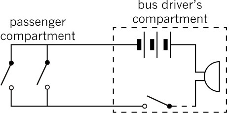
1. Write SW1 and SW2 next to the two switches for the passengers.
When school learners go on an excursion, they sometimes ring the bell many times just for fun. This prevents the driver from concentrating on the road, so he or she has a "master switch" to turn off the bell.
2. Which switch gives the bus driver control over the whole circuit? Write SWmaster next to that switch.
The passengers have OR-control because switch SW1 or switch SW2 can ring the bell. However, the driver has AND-control. For the bell to ring, SWmasterand one of SW1 or SW2 must be on.
3. Complete a truth table below for the bell circuit of the bus.
|
SWmaster |
SW1 |
SW2 |
output from the bell |
|
1 |
0 |
0 |
|
|
1 |
1 |
0 |
|
|
1 |
0 |
1 |
|
|
1 |
1 |
1 |
|
|
0 |
0 |
0 |
|
|
0 |
1 |
0 |
|
|
0 |
0 |
1 |
|
|
0 |
1 |
1 |
Write a design brief and specifications (15 minutes)
The scenario:
Mr Abdullahi has set up a shop. The customers are happy with his low prices. He sells food and clothing cheaply because he co-operates with other shopkeepers in the area. They work together to negotiate with the big suppliers of clothing and food to get cheaper prices.
Sometimes Mr Abdullahi is alone in the shop. If he has to work in the office at the back of the shop, he closes the two front doors of the shop, but the doors are not locked. He will only know if someone comes in at one of the doors if he sees them or if they call him.
Can you make him an alarm system that will tell him when a door opens? Sometimes Mr Abdullahi has an assistant in the shop, and then he does not need an alarm, so he wants a switch to turn the alarm system on and off.
1. Write the brief here. The design brief is a short statement that describes the need and what type of solution will meet that need.
Project brief:
I am going to design and make a
2. Now write specifications for the solution. Specifications have detail about the system you are going to make. Remember that the system:
- should make a sound when either one of the two doors are open, and
- should have a switch to turn the whole system off.
Specifications:
Investigate: components you could use (15 minutes)
1. What type of devices can you use for the alarm to make a loud sound?
2. What type of battery can you use? Remember that a 9 V battery will burn out motors that are rated for 1,5 V. Beepers also have their own voltage ratings, and you must find out what these are.
3. How can you make a switch that will close the circuit when the door is opened? Find a switch in this chapter or another chapter that will meet these requirements.
Design: draw a circuit diagram (15 minutes)
1. Should the alarm system use AND-control or OR-control? Explain.
2. Often designers look at circuits that have already been designed, to see whether any of those circuits will do the job. Look at Figures 7, 9 and 11 again. Which of these circuits will work?
3. Draw that circuit again in the space below. Give names for the different switches and show them as labels on your circuit diagram.

4. Show more information on your circuit diagram in Figure 12. Draw dashed lines around the part of the circuit that is in the front of the shop, and other dashed lines around the part that is in the office.
Hint: Look at Figure 11 again to see how dashed lines were used to show the part of the circuit in the bus driver's compartment.
Week 3
Design, make and communicate
Draw the layout of your alarm system in the shop(15 minutes)
Figure 13 shows a simple sketch of the shop.
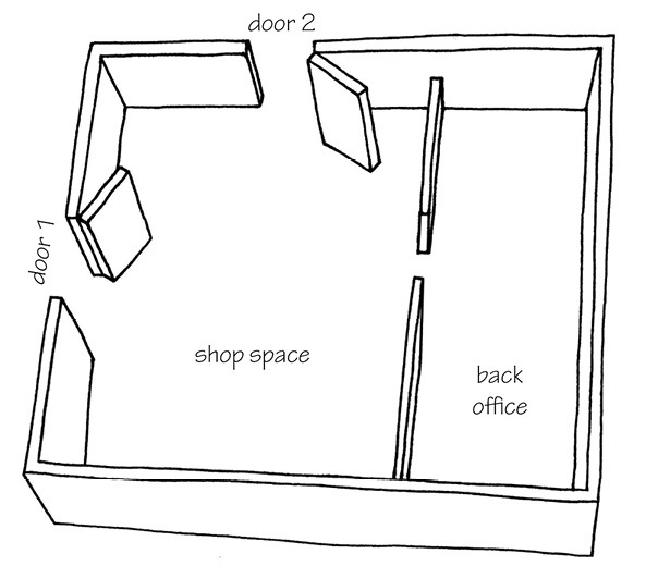
Draw on Figure 13 to show where you will put all the switches and other circuit components. Also show the connecting wires for the circuit. Put in labels for the circuit components. The circuit components should be connected as shown by the circuit diagram that you made for Figure 12.
Make a cardboard model of the shop (15 minutes)
Make a model of the shop out of a cardboard box. Cut two doors in the box. The model should not have a roof, so that you can see inside it. Make the model as simple as possible, otherwise you will not have enough time to finish building the alarm system.
Design a door-operated push switch (15 minutes)
Figures 14 to 16 show examples of how push switches that are off when they are pressed in can be made.
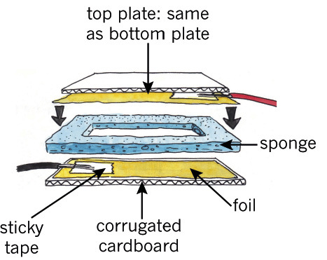
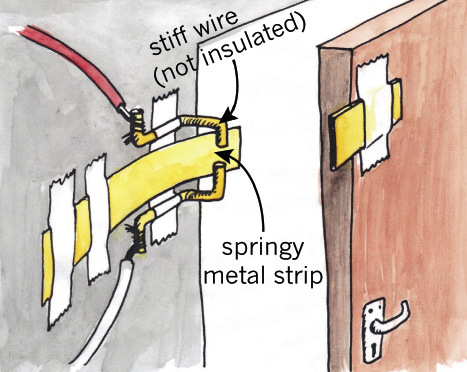
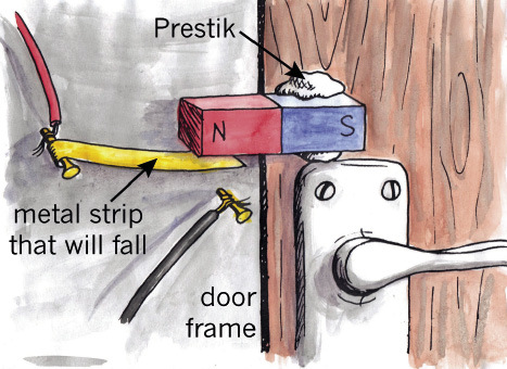
Use an idea or ideas from these examples to design your own door-operated push switch that is on when the door is open and off when the door is closed. Make a sketch of your design on the next page. Add labels to explain the different parts of your switch design.
Make the switches for your alarm system (30 minutes)
Make two of the door-operated push switches that you designed. Remember that they need to fit on the doors of your cardboard model of the shop.
Do not make a master switch, as you don't have enough time for that. You can simply connect two crocodile clips of conducting wires to "switch on" the master switch, and disconnect them to open the circuit and "switch off" the master switch.
Add your circuit to your model of the shop (30 minutes)
Now add all your circuit components and conducting wires to your cardboard model of the shop. Your design of the placement and wiring of the alarm system in Figure 13 will help you to connect all the circuit components in the correct way.
Stick the wires to the walls of the box with tape to make your model neat.
Connect all the circuit components.
In a real building, the alarm wires are stuck to the walls or are in the ceiling. The door switches are on the inside of the doors. If they were on the outside, a burglar could disconnect them.
Evaluate: test your alarm system (15 minutes)
When you evaluate the project, ask yourself: "Did I solve Mr Abdullahi's problem?" The following questions will help you to test whether your alarm fulfils all of the specifications. Do these tests:
1. Does the alarm make a noise when you open only door 1?
2. Does the alarm make a noise when you open only door 2?
3. Does the alarm make a noise when you open both doors?
4. Can Mr Abdullahi switch the system off and leave the doors open?
5. Complete a truth table for the system.
|
master switch |
switch 1 |
switch 2 |
output |
|
1 |
|||
|
1 |
|||
|
1 |
|||
|
1 |
|||
|
0 |
0 |
0 |
|
|
0 |
0 |
1 |
|
|
0 |
1 |
0 |
|
|
0 |
1 |
1 |
Homework: make an advertisement for your alarm system
Mr Abdullahi likes your system so much that he offers to advertise it to other shopkeepers. He thinks some of them will pay you to build and install alarms for them.
He asks you to make a poster that shows the shop and the doors, some of the parts of the alarm system, with a few sentences that explain how the system works.
Make a poster to advertise your alarm system on the next page. But first sketch rough ideas for your poster on this page.