Mini-pat: a mine needs a lifting system
This mini-PAT will run over four weeks. For this mini-PAT, you should form teams. Each team will pretend to be a mechanical engineering company. Each company will submit a tender for the design and construction of a "mine-lifting system", commonly called "mine shaft headgear".
The lifting system is used to take miners underground and back up again. It is also used to lift the mined ore to the surface. After you have designed your lifting system, you will have to make a model of it. The model will have a mine winch, shaft headgear and a lift cage.
Week 1
An opportunity to tender for a mining contract
Platinum, a very valuable metal, has been found on land belonging to a tribe in a rural area. Samples show that the platinum is only 500 m below the surface.
An international and South African joint venture company, called Platinum Stars, has decided to invest money in this project. They want to sink a shaft to the 500 m point to take a few samples. Then they will decide on the best mining method.
Your engineering company wants to submit a tenderfor the construction of the shaft headgear. The headgearmust be able to transport miners and equipment 500 munderground. It must also be able to lift platinum orethat weighs 10 tons back up to the surface.
A tender is an offer by someone to do work at a certain price. When a company "puts out a tender", it invites people to apply to do a job for them.
Headgears and mine winches
An overview of a mine shaft
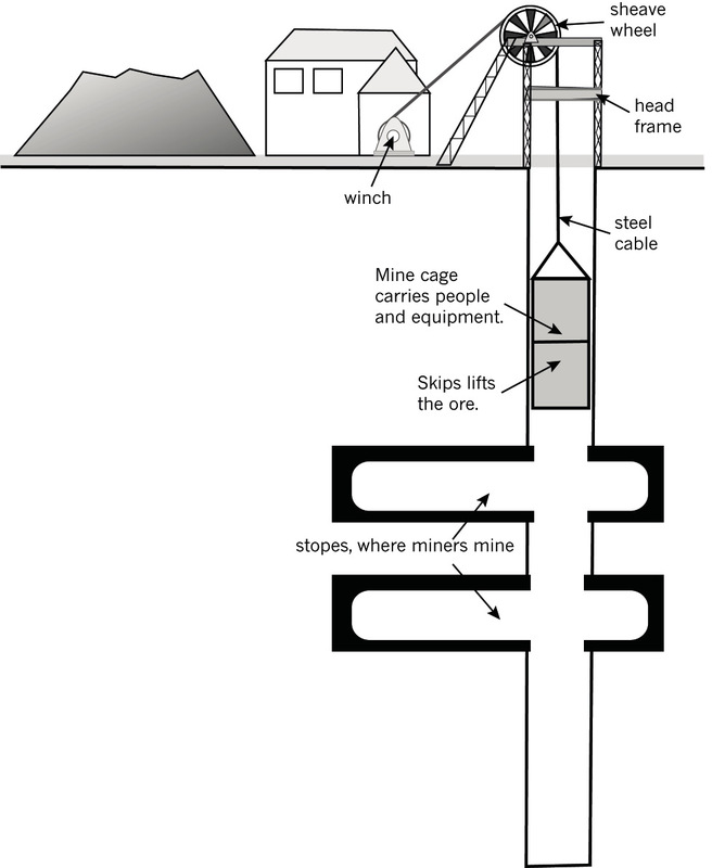
Study Figure 3 on the following page. This picture shows a mine's lifting system. The whole lifting system is called the headgear. There are four main parts to a mine's headgear:
Part 1: The winch or hoist is in a winding house. This part of the system is used to wind or unwind the steel cable.
The hoist is attached to a motor and a control system.
The mine cage and the skips are lowered into the mine when a steel cable unwinds from the winch.
The mine cage and skips are raised when the steel cable winds up again.
Part 2: The sheave wheel is a pulley wheel that sits above the mine shaft. The hoist cable passes over the sheave wheel and then down the shaft of the mine.
The sheave wheel reduces the sliding friction of the mine cable.
Part 3: The head frame is the structure that supports the sheave wheel. It must be strong enough to keep the sheave wheel in place when it lifts the heavy mine cage.
The left "legs" of the head frame slope towards the hoist. This is due to the tension in the cable pulling the whole frame in that direction. The sloping legs prevent the head frame from toppling or falling over.
Part 4: The cage and skips. The cage is used to transport miners and equipment up and down the mine. Attached alongside or underneath the cage are skips.
Skips are used to bring the ore and the waste rock out of the mine.
Investigate: mine shaft headgear and head frame (30 minutes)
Individual work
Use the picture in Figure 3 and your own information to answer the questions below:
1. What does the headgear of a mine do?
2. What happens in the winding house of a mine?
3. Explain what a sheave wheel is and what it does.
4. What does a head frame do?
5. Why do the legs on a head frame always slope towards the winch?
6. What do you call the two parts of the lift that goes down a mine?
7. What do these two parts of the lift do?
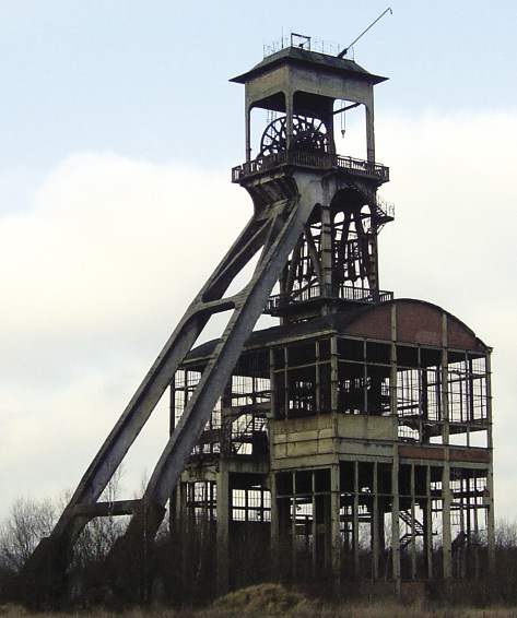
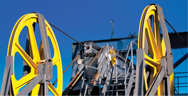
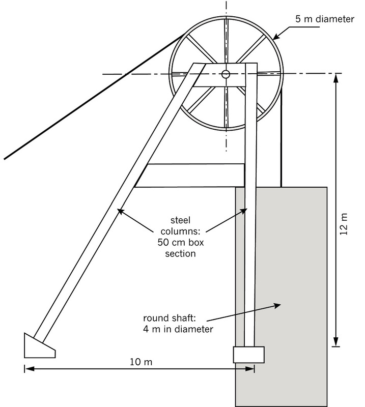
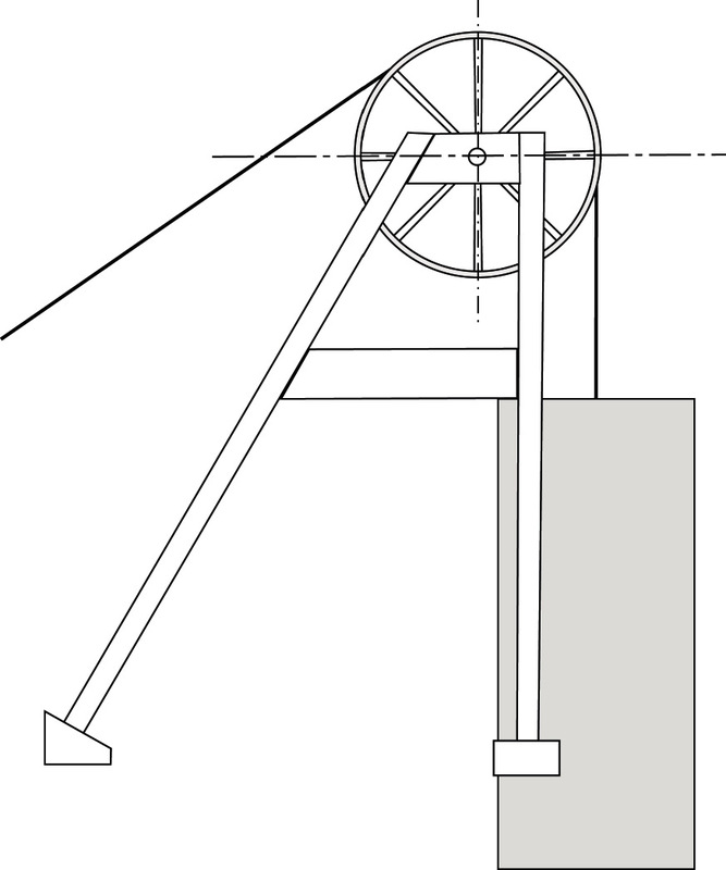
Look at the photograph in Figures 1 and 2. The photographs show the head frame and sheave wheel on the tower above a mine shaft.
Study the structure of the head frame and then answer the questions below. You will have to use your knowledge of frame structures to answer the questions.
8. Do you think I-beams are a good thing to use for head frame supports? Why?
9. Where do you see triangulation used on this structure? Explain how triangulation helps to make the head frame structure stronger.
10. What has been used to stop the head frame from being pulled over by the winch?
11. Look at the sheave wheel. Has it been placed in the middle of the upright column? Why do you think it is important to place the sheave wheel in exactly the right place on the head frame?
12. Make a 2D sketch of a head frame and sheave wheel in the space on thenext page.
Total [7]

Investigate: mine winches (30 minutes)
Individual work
Look at the pictures in Figure 4. The pictures show two different types of mining hoists. The first one has one sheave wheel, while the second has two sheave wheels. Use these pictures to help you answer the questions below:
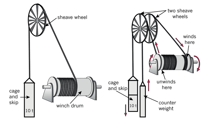
1. What are the differences between the two mine winches shown here? (½)
2. What do you think a counterweight does for a mine winding system?
Hint: imagine winding the winch by hand. (1)
3. If the mine winch drum diameter is 6 m, calculate how far the cage will drop for each single rotation of the drum. (½)
4. If the mine winch drum diameter is 6 m, calculate how far the counterweight will lift for each single rotation of the drum. (½)
5. Calculate how many turns of cable you will need on the drum for your cage and skip to move up and down by 500 m. (½)
6. Which of the two systems in Figure 4 do you think will need the largest motor? Explain your answer. (1)
7. Which system will be safer? Explain your answer. (1)
Total [5]
Design: design brief, specifications and constraints for a mine shaft headgear (60 minutes)
Individual work
Sketch a whole headgear solution that might impress Platinum Stars. You should mark your sketch with the approximate sizes for:
- the depth of the shaft,
- the carrying load of the skip and the mass of the counterweight,
- the approximate size of the winding drum,
- the approximate height of the headgear and the sheave wheel, and
- the approximate sizes of the mining cage and skip.
Note: You might have to do a bit of research on your own.
Have another look at the scenario titled "An opportunity to tender for a mining contract," at the start of this chapter.
Write the design brief. Use the following questions to help you:
1. What is the opportunity you are tendering for? (½)
2. What do you need to do to tender for this project? (½)
3. Write the design brief in the space below. Start your paragraph with:(1)
We are going to design and make ...
Write a list of specifications and constraints
4. Think about people: Write down at least two things that the mine winch system must do for people. How should it help the mineworkers? What should it do, or not do, for the local people who live near the mine? (1)
5. Think about purpose: What is the headgear for? What must it do? How fast must it travel? How far? How much weight does it need to carry? Write down at least two things about the purpose of this mine-winch system. (1)
6. Think about safety: What will happen if something goes wrong? What must your system have to try to prevent things from going wrong? What things must your system have to deal with emergencies when something does go wrong? Write down at least two things that will help to ensure that your design is safe. (1)
7. Think about the environment: Write down at least two things to help the environment when you design and make this headgear system. (1)
8. Think about appearance: Do you think appearance matters when you design something such as headgear? Can your head frame's appearance help you to win the tender? Write down at least two things about the way you want your headgear to look. (1)
9. Think about costs: What can you say about your costs for this project? Do you want the most expensive and the best of everything, or the cheapest and simplest, or something in-between? (1)
Total [8]
Next week
Next week, you will do Week 2 of your mini-PAT. You will form engineering companies, evaluate ideas and choose the best idea. You will draw your solutions and begin to prepare your company's tender.
Week 2
Your company prepares a tender
This is the second week of the mini-PAT for mechanical systems in Grade 8. During this week, you will form your own engineering company.
Then you will combine all of the ideas you came up with last week, and choose one idea to for your tender.
You will present this tender to the mining joint venture company, Platinum Stars, later in this mini-PAT.
Platinum Stars will only accept tenders from companies. That means that you cannot submit a tender as an individual person.
A company is formed when two or more people come together for business reasons or goals.
Your business goal will be to do engineering work for Platinum Stars.
Form a company(20 minutes)
Team work
1. Choose your company partners by arranging yourselves into teams of 3 to 5 people. Write down the names of each company member. This list of names will need to appear on your tender document. Also write your ID number next to your name.
2. Write a mission statement: Write one short sentence saying what your company will do, how you will do it, who you will do it for, and why you think you will be able to do it well. Start your sentence with the words:
‘We at Underground Mining Engineers aim to ...
Evaluate: choose and combine the best ideas (40 minutes)
Combine your specifications and constraints
Team work
Look at the specifications and constraints that you did last week. They won't be exactly the same. Make a new list that includes the best of everyone's specifications and constraints. Everyone in the team should write this list in their workbooks.
1. Think about people: (1)
2. Think about purpose: (1)
3. Think about safety: (1)
4. Think about the environment: (1)
5. Think about appearance: (1)
6. Think about costs: (1)
Total [6]
Combine your head frame and sheave wheel ideas
Individual work
Look at all the sketches you made last week of the head frame and sheave wheel. Use your specifications and constraints and discuss which combination of ideas will work best.
1. Now make a sketch of your company's final design in the space below.[5]
Make: draw your head frame (60 minutes)
Individual work
Look at Figure 5. It is a working drawing for a small head frame design.
This view shows:
- the size of the sheave wheel,
- the height of the sheave wheel, and
- the distance between the front and back legs.
1. Draw your head frame in the grid below. Use Figure 5 to help you. You should show all the dimensions for the main parts of your head frame design.
Note: You may need to add triangulation to make your structure stronger.
You don't have to draw this to scale.
Don't show dimensions. [4]

Make a 2D scale drawing
2. Now use rulers and set squares to draw a more accurate version of your company's head frame design. Use the grid below. [5]
Scale:
Suggested scale for a small head frame: 1 cm = 1 m.
Suggested scale for a larger head frame: 1 cm = 2 m.
Make a 3D isometric drawing
The picture in Figure 6 shows a 3D isometric view of a head frame design. The drawing has been done on isometric grid paper, using instruments such as rulers and setsquares.
Isometric means equal measure.
One little triangle in this grid, represents 50 cm in each direction of the real structure.
That means that a line that crosses 10 triangles is 500 cm or 5 m long.
This view shows all three dimensions of the structure. You can see the sizes and the detail of the height, width and length.
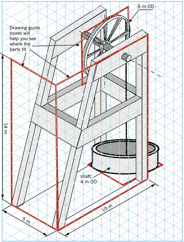
3. Make a 3D drawing of your own head frame on the isometric grid below. [6]

Total [15]
Week 3
How much will it cost?
To win a tender, you will have to show that your design is going to be the best and the best value for money. The table on the next page will help you to work out a tender budget.
Design: make a list of materials and work out thebudget(30 minutes)
Individual work
Hints:
- Look at your head frame drawing. Calculate the total length of steel column you will need for the legs of the head frame. Then enter the total length into the Quantity Needed row of the table. Calculate the cost of the total length of steel columns that you need to buy and enter the amount into the table.
- Calculate the total length of steel you will need for the cross braces and enter this total into the table. Calculate the cost of the steel needed for bracing.
- Complete the rest of the table. Enter quantities you will need and calculate the cost estimate for each item.
- Your project advisor says that you will need one project manager, one engineer, four artisans, four semi-skilled workers and 12 unskilled workers on the project, and that it will take six months to complete. Calculate the labour cost estimate for each of these workers.
- Calculate the "subtotal" for each of the three cost categories, namely "steel for the head frame", "lift components" and "labour".
- What will your total project cost be? Add up all of the subtotals of the different cost categories to calculate the total project cost.
Mark allocation
- good estimates of materials quantities(1)
- correct calculation of labour quantities (person/hours) (1)
- calculations of cost estimate per item(2)
- calculation of subtotal and total project cost(1)
Total [5]
|
Item |
cost per unit |
quantity needed |
cost estimate |
|
Costs of steel for the head frame |
|||
|
steel column |
R500 per metre |
||
|
steel for cross braces |
R20 per metre |
||
|
Sub-total: Costs for steel frame |
|||
|
Costs of lift components |
|||
|
sheave wheels |
R 150 000 |
||
|
winch and motor |
R 1 200 000 |
||
|
cable |
R 100 per metre |
||
|
cage and skip |
R 350 000 |
||
|
Sub-total: Costs of lift components |
|||
|
Labour costs |
|||
|
project manager |
R 30 000 per month |
||
|
engineers |
R 30 000 per month |
||
|
artisans |
R 25 000 per month |
||
|
semi-skilled workers |
R 20 000 per month |
||
|
unskilled workers |
R 12 000 per month |
||
|
Sub-total: Labour costs |
|||
|
TOTAL PROJECT COST: |
|||
Make a model head frame (30 minutes + 60 minutes)
Team work
Now it is time to make a model of your head gear. You will need to make several different parts:
- the head frame with its sheave wheel,
- the mine winch, and
- the model lift.
In this activity, you will make the first part, the head frame.
Remember: Your teacher will watch you while you make your model to see how well you:
- work as a team,
- measure and mark things properly,
- cut and join parts accurately and with thecorrect tools,
- finish and decorate your model, and
- use safe working practices.
Safety tips:
Never play with cutting tools. Never point the sharp end at someone else. Keep your tools neat and clean and in good working order. Do not spill glue or leave the lid open as the fumes are poisonous.
Not everything you try will work well. So don't beafraid to change your designs to improve them as you go along.
Make the steel columns
You can make your steel columns using cardboard. Look at Figure 7 to help you. You can make round or rectangular columns depending on the former you use:
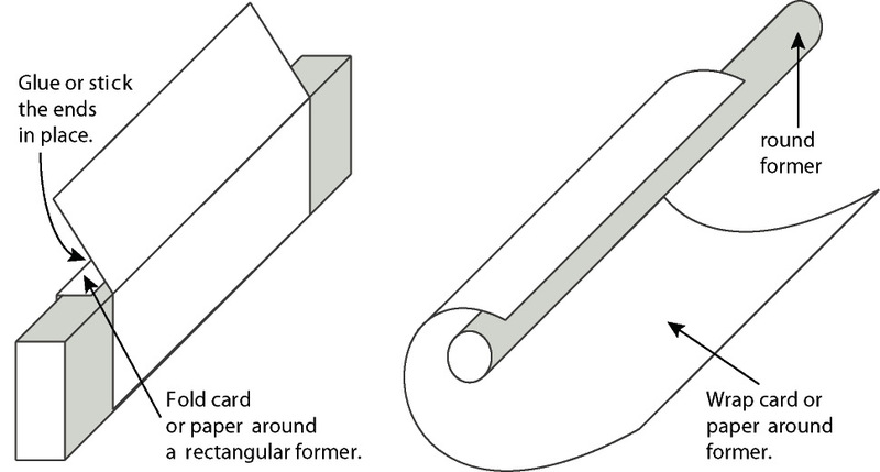
- If you use a rectangular former, you will get a channel. A strip of wood 2 cm × 1 cm will workwell for this.
- If you use a round former,
you can make roundcolumns out of cardboard. A 10 cm
dowelworks well for this.
A former is a shape that can be used to make tubes. For example, when you wrap a flat sheet over a rectangular former, you make a tube with a rectangular cross section.
1. Choose how you will make your columns and thenmake all the pieces you will need for your model. Have another look at Figure 7 to help you. (1)
Make the cross braces
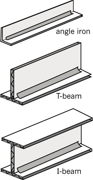
You can make cross braces by joining flat pieces of corrugated cardboard together. You can use tape or glue to join the flat pieces. Look at Figure 8 to help you. Figure 8 shows three types of cross braces: angle irons, T-beams and I-beams.
2. Decide which of these cross braces you need for your head frame. Then make the cross braces you need. You will use these cross braces and the columns you made earlier to make a model of your head frame. (2)
Make flat frames
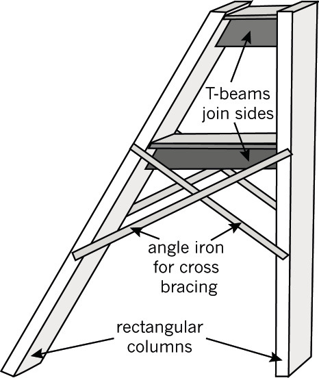
Look at Figure 9. This figure shows one side of a frame.
- T-Beams have been used to join the vertical and the sloping column.
- Cross bracing has been added to strengthen the lower half of the frame.
3. Carefully cut your beams to the right size and shape to fit neatly between the columns. Then glue or tape them on. (2)
4. Cut your angle sections so that they can fit across the columns. Trim the ends so that the outside of the angle can be joined to the side of the column, but remember that the angle has to fit neatly between the columns. (2)
5. When you are happy with your first side frame, make the second inexactly the same way. (1)
Join your side frames
6. Now make your head frame by joining your two side frames together. (2)
Make a sheave wheel
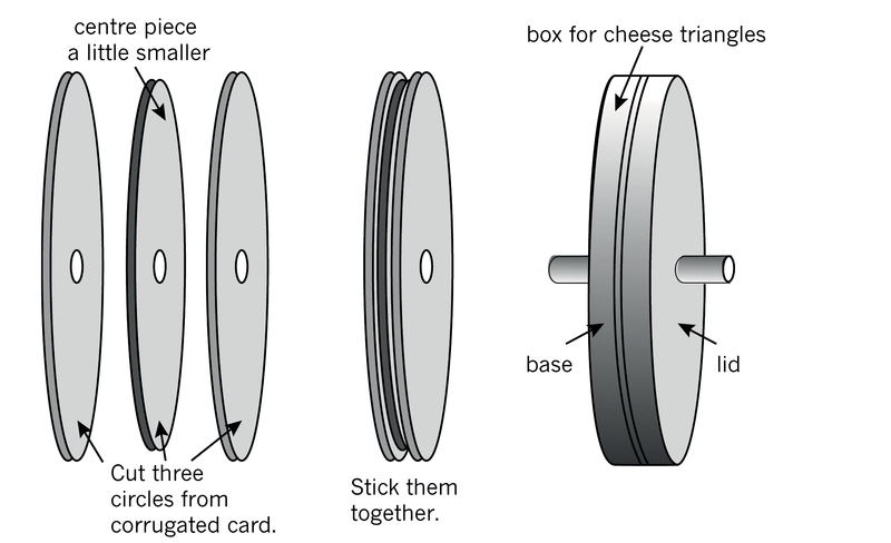
Look at the pictures shown in Figure 10. They show two ways to make a model sheave wheel:
- You can use a round cardboard box, such as the ones used to pack cheese triangles.
- You can cut three circles from corrugated cardboard and sandwich them together.
For both methods, a plastic straw has been used to make a bearing through the middle of the wheel. This bearing will make the wheel turn easily on its axle or shaft.
7. Make you own sheave wheel. Try to make it as close to the correct scale size as you can. Use Figure 10 to help you. (1)
Mount the sheave wheel on an axle and fit it to the frame
Your sheave wheel has to turn easily. It needs to have an axle passing through the centre of the wheel. You can use a dowel stick, about 4 mm in diameter, or a long nail (about 60 cm long) for your axle.
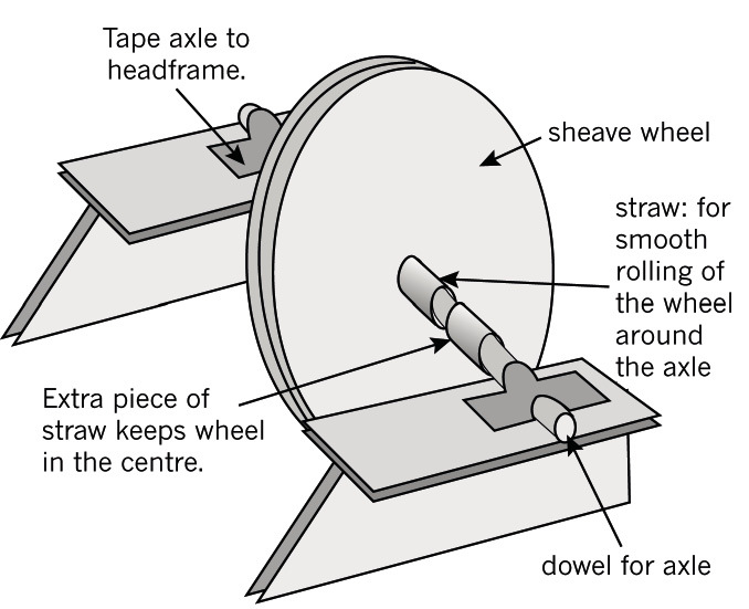
Look at the picture in Figure 11. A sheave wheel has been added to the top of a head frame in the following way:
- The axle is taped onto the top of the head frame.
- The wheel, with a straw through its centre, can rotate freely on the axle.
- Extra pieces of straw have been added to keep the wheel in the centre of the axle.
8. Now add your sheave wheel to its head frame. Use Figure 11 to help you. (2)
Will your axle bend? Have a look at the axle supporting your wheel. This axle will have to carry all the weight of the lift. Does it have enough support? If the distance between the axle and the supports are too long, then it will bend and might break.
If you need to, add extra supports for the axle at the top of the head frame.
Total [13]
Next week
Next week, you will complete your mini-PAT. You will make a winch and a lift and then you will present your tender.
Week 4
Communicate a headgear tender
This week is the last week of your mini practical assessment task for mechanical systems in Grade 8.
You will make your mine winch and add it to the head frame you completed last week. Then you will add a lift, commonly called a cage, to your model.
After testing your system and adjusting it, you will collect all the work you have done so far for this mini-PAT, and use it to prepare a tender presentation to present to the tender board of the Platinum Stars Mining Company.
Complete your model: make a winch and cage (20 minutes)
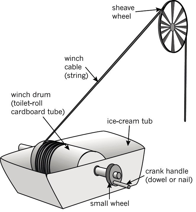
Do you remember investigating crank winches in Chapter 4 and in this chapter? Look at Figure 12 again. It shows you how to make a model mine winch yourself.
- The winding drum for this mine winch was made from a toilet-roll cardboard tube.
- The winch drum has been put onto a 2 l plastic ice-cream tub. This will be the winch house.
- This winch does not have a motor attached. Instead it uses a crank handle. But if you have a motor, then you can connect a belt drive or a gear system to the winch's drive wheel instead.
Here are a few important things to remember when making a mine winch such as this one.
- The drum has to turn when the crank handle isturned. That means that the shaft that connectsthe small wheel with the crank handle to thewinding drum must be tightly attached to thedrum, and to the drive wheel. You can use glueor tape to make sure that the shaft is firmly stuck onto the drum and wheel.
- The shaft must be able to
turn easily in the holes on the sides of the ice-cream
container.
Shafts and axles:
The centre of a wheel is called a shaft when it turns with the wheel.
When the centre of the wheel stays still and the wheel slides over it, it is called an axle.
- The rope or string must be firmly attached to the winding drum and it must not be able to come off. Imagine what would happen to the lift cage if it did.
1. Make a winch drum of your own. Remember it must be able to lift and lower a cage into the mine.
Will your cage be square or round? You can use a paper-towel tube for a round cage or any square box for a square cage. Tie your lift cage to the shaft side of the sheave wheel. [2]
Test your head gear
With your cage and your winch attached to the head frame, you now have a complete system. Test your system to ensure that you can lift and lower miners, and lift mined ore from a shaft underground.
Evaluate the head gear (10 minutes)
Evaluate your solution
Look at the model your team has made.
1. Do you think the head gear is suitable for transporting miners to a depth of 500 m underground, and for lifting mined rock samples from underground? Explain your answer.
2. What have you done to ensure that your system will be safe?
3. What have you done to make your headgear look good so that the community will not complain about the mine ruining the area?
4. Do you think the environment will be damaged in any way by your structure?
5. Why should the tender board choose your head gear?
6. Are there any things the tender board won't like?
Present your solution to platinum stars (90 minutes)
Prepare your tender
1. Prepare a team presentation to the tender board of the Platinum Stars Mining Company. Each member of your team should talk about one of the points below:
- Your head frame ideas. This person should show the sketches and drawings you did while designing your head frame.
- Your winch idea. This person should show the sketches and drawings you did while designing your mine winch.
- The budget. This person should talk about the costs of making your headgear.
- Why the tender board should choose your solution. This person should use your 3D model to convince the tender board that your solution is the best.
Present your tender
2. Now present your tender bid to the tender board. (3)
Evaluate different tenders
3. While listening to other people's tender presentations, write down some of the best points about their tenders.
4. Which tender do you think should win? Explain your decision.
Remember: To be good at evaluating you must show that you can judge other people's work objectively. (1)
Total [4]