Levers, linkages and gears
In this chapter, you will revise what you learnt in Grade 7 about different types of levers and linked levers. You will pay special attention to whether a lever or a system of levers gives a mechanical advantage or a distance advantage.
You will also revise what you learnt earlier this year about how gear systems can give a mechanical advantage or a speed advantage. Then you will learn about a type of gear called a bevel gear. Bevel gears change the direction of rotation.
It is important that you understand mechanical advantage very well, because you will be doing calculations about mechanical advantage in the next chapter.
Revision of levers and mechanical advantage
Mechanisms are parts of machines that help us to move things. Machines are usually made of many connected mechanisms. Some parts of a mechanism move, and other parts are used to hold the moving parts in place.
Mechanisms are useful because they help us to move things further, faster or by using less force.
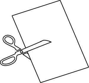
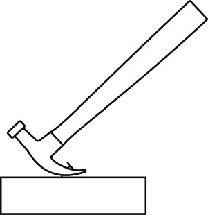
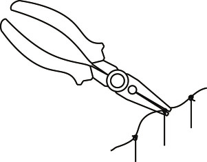
Figures 4 to 7 show machines that you might have at home. Write down what each of these machines is used for, and how they make it easier to do the task.
1. A bottle opener
2. A pair of scissors
3. A hammer
4. A pair of pliers
Levers allow you to change the direction of movement, the size of movement and the amount of input force that is needed for the output movement to happen.
Do you remember what mechanical advantage is?
You already know that:
- If the input force is smaller than the output force, there is a mechanical advantage. You can say the mechanical advantage is bigger than 1.
- If the input force is bigger than the output force, there is not a mechanical advantage, but rather a distance advantage. You can say the mechanical advantage is smaller than 1.
When engineers, scientists and technologists design mechanisms, they want to know exactly how big the mechanical advantage in a system is. It is not good enough for them to say that the mechanical advantage is bigger than 1 or smaller than 1. They need a number to tell them exactly how big or small the mechanical advantage is. We call this number the mechanical advantage.
You can use the abbreviation MA for mechanical advantage.
The mechanical advantage is calculated by dividing the output force by the input force: \(\text{mechanical advantage } = \text{ output force} \div \text{ input force } = \frac{\text{output force}}{\text{input force}} \) You can also say that the mechanical advantage is the ratio between the output force and the input force.
If a lever makes it easier to lift a heavy weight, the input force is less than the output force, and the mechanical advantage is greater than 1.
For example, if the output force is 12 and the input force is 4, the mechanical advantage is calculated in the following way:
\(12 \div 4\). This can also be written as \(\frac{12}{4}\) or 12⁄4
The answer to this calculation can be written in different ways:
a ratio of 3 to 1
OR 3 : 1
OR 3.
These different ways of writing the answer all mean the same thing: they are equivalent. You can write an equals sign instead of "OR" between the different ways of writing the answer, because they are equivalent.
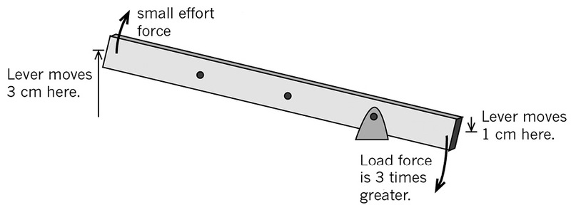
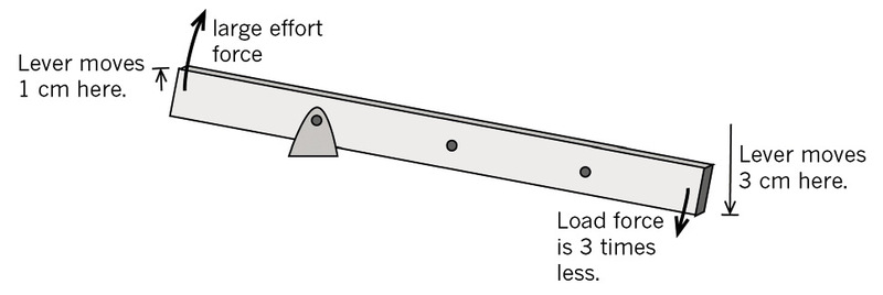
This means that the output force is threetimes greater than the input force. You can also saythat the lever gives a mechanical advantage of 3.
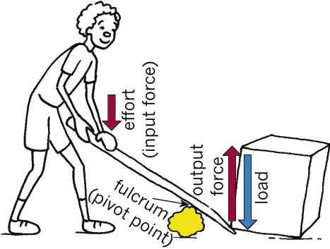
But you cannot get something for nothing. If the input force is 3 times less than the output force, you will have to move the input arm 3 times further than the output arm. Look at Figure 8 to see how this works.
Not all levers give a mechanical advantage. Sometimes the input force is greater than the output force. These levers make it harder to move something, but the output movement will be greater than the input movement.
If a lever makes it harder to lift a heavy weight, the input force is greater than the output force, and the mechanical advantage will be less than 1. If, for example the input force is 3 and the output force is 1, the mechanical advantage is output force ÷ input force = ⅓, in other words 1 third.
In the example above, the output force is only 1 third as big as the input force. The output arm will move 3 times further than the input arm. In other words, this lever gives a distance advantage of 3. Look at Figure 9 to see how this works.
When a mechanical system changes a small input distance into a larger output distance, the system gives a distance advantage.
On a lever, the distances moved by the input arm and the output arm are directly related to their distances away from the fulcrum.
- If the distances from the fulcrum are equal, the distances moved will be equal.
- If the fulcrum is closer to the input force, the distance moved by the input arm will be smaller.
- If the fulcrum is closer to the output force, the distance moved by the output arm will be smaller.
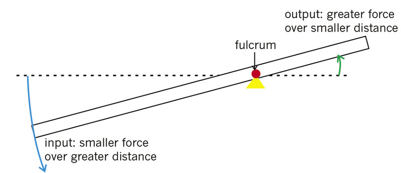
If the distance between a fulcrum and the output is less than the distance between the fulcrum and the input, the output force will be greater than the input force and the lever gives a mechanical advantage. If the distance between a fulcrum and the output is greater than the distance between the fulcrum and the input, the output force will be less than the input force and the lever gives you a distance advantage. In this case, you will not get a mechanical advantage.
The first-class lever and mechanical advantage
A lever can change a large movement with a small input force into a small movement with a large output force. When you use a bottle opener, you use a small input force to pull up the long handle, and the lever mechanism makes the output force big enough to bend the top of the bottle.
If MA > 1, then a small input force over a big distance at one end, can move a bigger output force over a shorter distance at the other end. The bottle opener, scissors, hammer and pliers in Figures 4 to 7 are examples of this.
The first-class lever and distance advantage
You can also use a lever the other way around. You can use a big input force over a small input distance. This gives a smaller output force over a bigger output distance. You can see this in Figure 11.
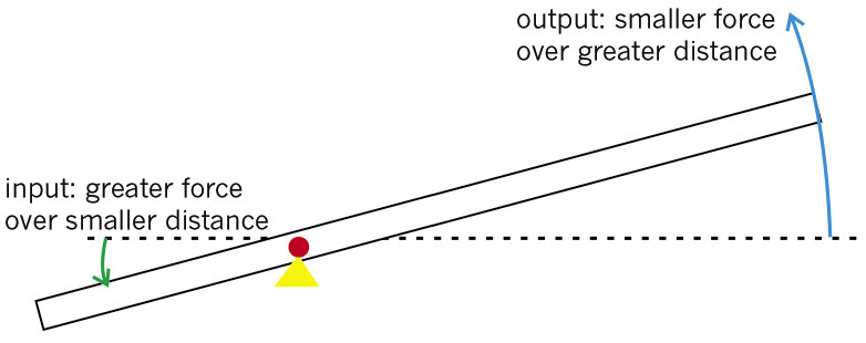
These kinds of levers are often used to help cranes lift things very high. If, for example, the input arm moves 1 cm down and lifts the output arm 4 cm up, the lever is giving you a distance advantage. But the input force has to be 4 times bigger than the output force, so the mechanical advantage is less than 1:
MA = output force ÷ input force = ¼ = 1 quarter. When the MA < 1, there is not a mechanical advantage, but rather a distance advantage. A big input force over a small distance at one end, produces a smaller output force over a bigger distance at the other end.
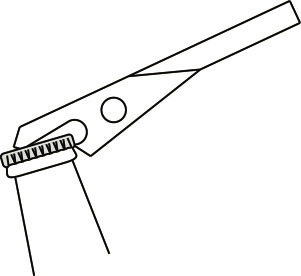
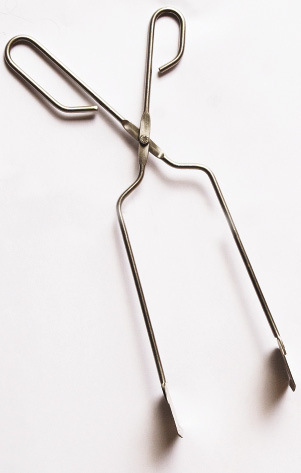
The pair of kitchen or braai tongs in Figure 12 is an example of a tool that gives a distance advantage.
Linked levers
Figures 13 and 14 show two types of tools that are used to cut twigs and branches from trees, called "pruning".
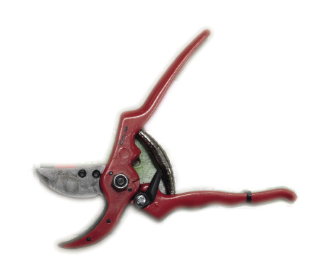
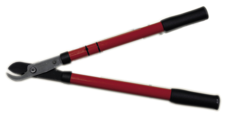
1. How do you know that both of these tools use levers?
2. How do you know that the levers used are first-class levers?
3. Do both of these tools give a mechanical advantage? Explain your answer.
4. Which of these tools will give you greater mechanical advantage? Explain your answer.
All frst-class levers have the fulcrum between the input and the output.


First-class levers
The fulcrum or pivot point is the fixed point on a lever. The lever doesnât actually go up or down at the fulcrum point. All the other points on a lever rotate around the fulcrum.
In a first-class lever, the fulcrum is always between the input and the output.
The input force is the force that you apply to a lever to make it move.
The output force is the force that the lever exerts on the load.
Systems of linked levers
A lever system that consists of more than one pair of levers that are connected to one another, is called a system of linked levers.
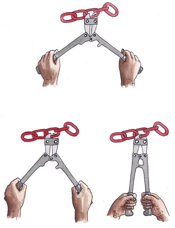
The bolt cutter in Figure 17 has two pairs of linked levers that are connected to each other. Figure 2 at the start of the chapter shows the movement of the parts of a bolt cutter.
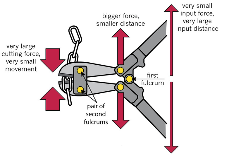
- The pair of dark grey levers on the right have the handles on them. They share a single fulcrum.
- The pair of light grey levers on the left have the cutting blades on them. They have a separate fulcrum for each lever.
- There are also two pivot points in the middle of the two pairs of levers, to link them together. They have a different purpose from the other fulcrums, because they move together with the levers, instead of the levers rotating around them.
1. Are both the pairs of levers used in the bolt cutter first-class levers? Explain your answer.
2. What can you say about the total mechanical advantage of the two pairs of levers linked to each other?
3. Look at the cutting levers (the end that cuts). What is different about the fulcrums of these levers compared to a pair of scissors?
4. Compare the arrangements of the fulcrums in the bolt cutter and the pair of scissors. Why are the fulcrums arranged in a different way in a bolt cutter than in a pair of scissors?
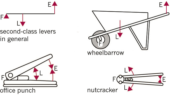
Second-class levers give a mechanical advantage
Second-class levers have the fulcrum at one end and the input at the other end. The output is between the input and the fulcrum.
A second-class lever always gives a mechanical advantage. The input is always further away from the fulcrum than the output, so the input arm always moves further than the output arm. This means that the output force will always be bigger than the input force.
So the MA is always greater than 1:
MA = output force ÷ input force > 1.
Second-class levers always give > 1.
1. Give one more example of your own for each of the following types of levers.
(a) first-class lever
(b) second-class lever
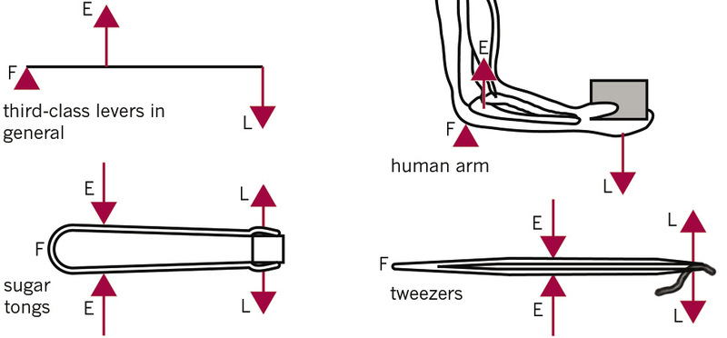
Third-class levers give a distance advantage
Third-class levers also have the fulcrum at one end, but the output is at the other end. The input is between the fulcrum and the output.
The input is always closer to the fulcrum than the output, so the output arm always moves further than the input arm.
This means that the output force will always be smaller than the input force.
So the mechanical advantage is always smaller than 1:
MA = output force ÷ input force < 1.
Third-class levers always give < 1.
Gear systems
You learnt about gears in Term 1 this year. Do you remember? Here are a few reminders:
Mechanical advantage and speed advantage
Gears are wheels with teeth. They can increase or decrease the turning speed of a wheel or axle.
The teeth of two gears mesh together so that if one gear turns, the other gear will turn as well, in the opposite direction.
- A small driver gear connected to a large driven gear will change a fast turning speed into a slower turning speed. This gear system will make the wheels turn with a greater turning output force than the input turning force of the motor. This system gives a mechanical advantage.
- A large driver gear connected to a small driven gear will change a slow turning speed into a faster turning speed. This system gives a distance or speed advantage.
You can also call turning speed the speed of rotation.
Mesh means that the teeth of the gears fit in-between one another.
Torque and revolutions per minute
A turning force is called a torque. The speed of a turning wheel is measured in revolutions per minute, or rpm.
A small driver and a large driven gear
Look at the two connected gears in Figure 20. Gears that have teeth like these are called spur gears. Now answer the questions that follow:
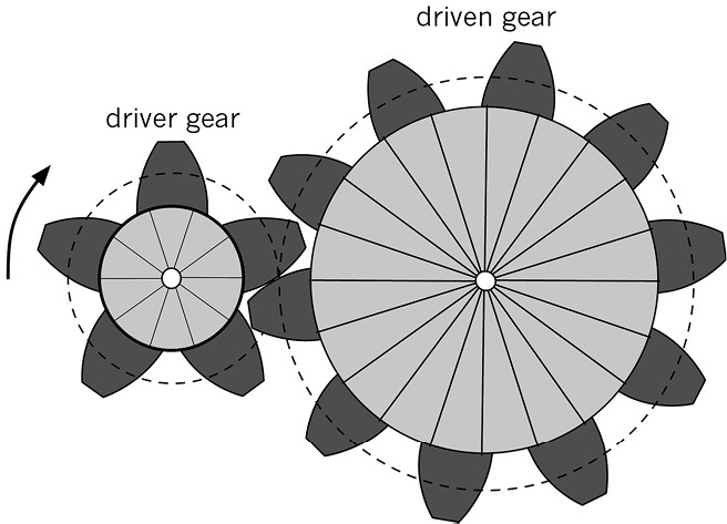
1. If the driver gear turns clockwise, which way will the driven gear turn?
2. Count the numbers of teeth on the two gears in Figure 20. How many revolutions will the driver gear need to turn to make the driven gear turn once? Explain why this happens.
3. Will this system give a mechanical advantage? How do you know?
Reminder: A mechanical advantage means that the turning force at the output axle is greater than the turning force at the input axle.
A large driver and a small driven gear
Look at the two gears in Figure 21. The driver gear is now large and the driven gear is smaller.
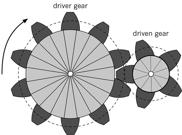
1. Will the driven gear turn faster or slower than the driver gear? Explain your answer.
2. A driver gear has 10 teeth and the driven gear has 5 teeth. How many revolutions will the driver gear need to turn to make the driven gear turn once? Explain why this happens.
3. Will this gear system give a mechanical advantage or a speed advantage? How do you know?
Reminder: A speed advantage means that the speed of rotation of the driven axle (output axle) is faster than the speed of rotation of the driver axle (input axle).
Idler gears
Look at Figure 22. The driver and the driven gear are the same size. In the middle there is a small gear called an idler gear.
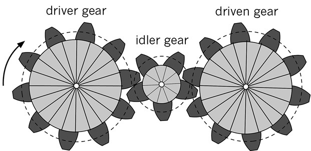
What does an idler gear do?
An idler gear is a gear that turns between a driver and a driven gear.
It allows the driver and the driven gears to turn in the same direction. An idler gear does not change the mechanical advantage of a gear system.
When two gears mesh, they turn in opposite directions. This is called counter rotation.
When an idler is used between two gears, the direction of rotation of the driver and driven gear is the same. This is called synchronised rotation.
1. Will the idler gear turn faster or slower than the driver gear? Explain.
2. Will the idler gear turn faster or slower than the driven gear? Explain.
3. Will the driver gear and the driven gear turn at different speeds? Explain.
4. Will the driver gear and the driven gear turn in different directions? Explain.
Bevel gears
Bevel gears are used when you want to change the direction of turning. Look at Figure 23. It shows how two bevel gears mesh together.
- The top gear will turn on a horizontal axle.
- The bottom gear will turn a on a vertical axle.
- The bevel gear system changes the direction of rotation by 90°.
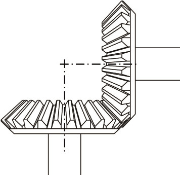
Horizontal means parallel to the ground. Vertical means at 90° (at a right angle) to the horizontal direction.
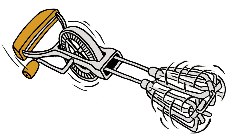
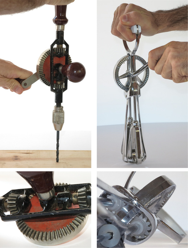
Figure 24 on the next page shows a hand drill and an egg beater.
- The driver gear is a large bevel gear attached to a crank handle.
- The driven gears are the small bevel gears. The bottom bevel gear forces the drill to turn and the egg beater to rotate its blades.
1. Do you think the hand drill gives you a speed advantage or a mechanical advantage? Explain your answer.
2. Explain how the bevel gears on the drill work.
Something you could do at home: make a can crusher
The lever on a real crane lifts a weight or load. The lever helps to lift the load higher. Levers are also used to squeeze or crush things. In this investigation, you will look at how a second-class lever can help you crush metal.
Many metal-working machines use levers to increase the input force, and the greater output force is used to cut metal sheet or to make holes in steel plates.
Empty cool-drink and food cans are waste that take up a lot of space. But it does not have to take up so much space, since most of the volume of a can is taken up by the air inside it. If you crush it, it will take up very little space. Before cans are recycled to make new steel, they are crushed. It's much cheaper to transport the crushed cans to a recycling factory since they require less space and you can transport more at a time.
Design a second-class lever to crush cool-drink and food cans. Make a rough sketch showing the dimensions. You can make this crusher from pieces of wood.
Next week
Next week, you will learn how to do mechanical advantage calculations for levers and gears.