What are the parts that make up this system for transferring electrical energy?
They are the battery, conducting wires, light bulb and switch.
Chapter overview
3 weeks
This chapter builds on the work done in Grade 7. In Grade 7, learners investigated basic circuits, as well as energy transfers within a system. In Grade 8, learners will practice drawing electrical circuits using the correct circuit symbols. This was first introduced in primary school, so learners should be familiar with the circuit diagram symbols, however, some revision might be necessary. It is important to remind learners that circuit diagrams are just schematics of a circuit. When building a real circuit from a diagram, the real circuit will not look exactly the same as the diagram.
A common misconception which develops in circuit building is that black wires carry negative current and red wires carry positive current. This happens because of the colour coding often used on electrical meters to indicate polarity. In order to avoid this misconception, sometimes red wires can be used to connect the negative side of the battery to the negative side of the meters, or sometimes only use one colour of wire. This shows that the colour coding is arbitrary.
If you do not have sufficient equipment to allow all the learners to make all the circuits or you want to experiment with simulations, you can use the PhET simulation for building an electric circuit. You can use the PhET simulation software which can be downloaded from
http://phet.colorado.edu/en/simulation/circuit-construction-kit-dc. You can then run an offline version on your computers.
Alternatively, if you have an internet connection, or if learners wish to use their mobile phones, these simulations will run directly within your browser from our website,[link]www.curious.org.za
Before allowing your students to use the PhET simulations there are several things you should familiarise yourself with regarding the software. Make sure you know how to:
If you only teach Natural Sciences, it is a good idea to check with the Technology teachers to see how these two curriculums complement each other, especially with regard to electricity. Some of the concepts which might be introduced for the first time in Natural Sciences, have already been covered in the Technology curriculum. Knowing what learners have already covered and been introduced to will help make your classes more efficient and more stimulating for learners.
2.1 Circuits and current electricity (1 hour)
Tasks | Skills | Recommendation |
Activity: A simple circuit | Recalling, identifying, interpreting, explaining | Suggested |
2.2 Components of a circuit (2 hours)
Tasks | Skills | Recommendation |
Activity: Components in an electric circuit | Recalling, identifying, drawing | CAPS suggested |
Activity: Recycling of batteries | Research, working in groups, explaining, writing | Suggested |
Activity: Resistance in a light bulb | Identifying, reasoning, interpreting, explaining | Suggested |
2.3 Effects of an electric current (6 hours)
Tasks | Skills | Recommendation |
Activity: Heating a wire in a circuit | Following instructions, observing, interpreting, explaining | CAPS Suggested |
Activity: Melting metal? | Following instructions, observing, interpreting, explaining | CAPS suggested |
Activity: How are fuses used in everyday circuits? | Research, explaining, writing | CAPS suggested |
Activity: Playing with plotting compasses | Drawing, describing, interpreting | Suggested |
Activity: Magnetic field around a conductor | Following instructions, drawing, describing, interpreting, explaining | CAPS suggested |
Activity: Making an electromagnet | Following instructions, interpreting, describing | Suggested |
Activity: Research the use of electromagnets | Research, working in groups, summarising, writing | CAPS suggested |
Activity: Electrolysis | Observing, interpreting, describing, explaining | CAPS suggested |
In the last chapter we looked at static electricity. We are now going to focus on current electricity. You will already be familiar with some of the concepts and terminology about electricity from previous grades. This year we are going to revise some of these concepts and also extend our knowledge about electricity.
There is no need at this level to discuss the idea of conventional current. The idea of conventional current (the movement of positive charges) was developed prior to the discovery of electron movement. It was adopted as a convention so that all scientists working with electricity could communicate and compare research with ease. The mathematical models of electricity are also simpler when considering conventional current. The idea of conventional current and SI units and their importance will only be discussed in Grade 9.
Revise a simple circuit. [video)
An electric current is the movement of charge in a closed, conducting circuit. As we know from Chapter 1, and also from Matter and Materials, the electrons in an atom are arranged in the outer space around the central nucleus. We saw in the last chapter how electrons can be transferred between objects resulting in a charge on the object. In metals, the electrons are able to move freely within the metal. The electrons are not associated with a particular atom in the metal. We say electrons in a metal are delocalised. Have a look at the following diagram which shows this.
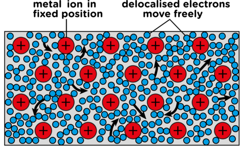
An ion is an atom that has a charge due to the loss or gain of electrons. Here the metal ions are positive as the electrons are delocalised.
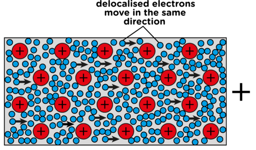
Conducting wire in an electric circuit is made of metal. If we supply it with a source of energy and a complete circuit, then the electrons will all move in the same general direction through the wire. This movement of electrons through a conductor is electric current.
Do you remember what you learned in Grade 6 and 7 about circuits? Let's revise briefly:
An electric circuit needs a source of energy (a cell or battery).
A circuit is a complete pathway for electricity.
The circuit must be closed in order for a device to work, such as a bulb which lights up.
We can say that an electric circuit is a closed system which transfers electrical energy.
A circuit is made up of various components, which we will look at in more detail.
Electricity and circuits (video)
INSTRUCTIONS:
QUESTIONS:
Some of these questions are revision of what learners should have covered in Gr 7 CAPS about energy transfers within a system. This acts as a revision exercise and to links back to prior knowledge to reinforce learning.
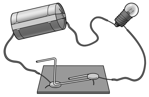
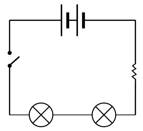
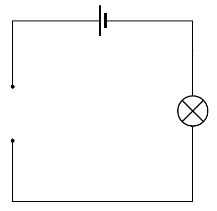
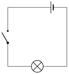
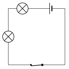
What are the parts that make up this system for transferring electrical energy?
They are the battery, conducting wires, light bulb and switch.
Do you think this is an open or closed circuit? Explain your answer.
It is closed as the switch is closed so it is a complete, unbroken pathway.
Which part is providing the source of energy?
The battery.
What is the conducting material?
The wires, made of metal.
What type of energy does the battery have?
Chemical potential energy.
What is this energy transferred to when the circuit is closed and the electrons move through the wires?
Potential energy is transferred to kinetic energy of the electrons.
What is the output of this system?
The bulb lights up, so it is light (and also heat).
In most systems, the input energy is more than the useful output energy as some of the input energy is transferred to wasted output energy. In this simple circuit with a light bulb, what is the wasted output energy?
The wasted energy is heat.
A complete circuit is a complete conducting pathway for electricity. It goes from one terminal of a cell along conducting material, through a device and back to the other terminal of the cell. Let's look at the components of a circuit.
You are probably already familiar with the components of an electric circuit from previous grades. Do you remember that we have a specific way of drawing the components in a circuit in an electric circuit diagram? Each component has a different symbol.
Complete the following table. List the function of the component and draw the circuit symbol. The last two rows have been filled in for you as you may not yet know these symbols, but we will be using them in this chapter.
Component | Function | Symbol |
Cell | ||
Torch bulb | ||
Open switch | ||
Closed switch | ||
Electrical wire | ||
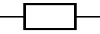
Resistor | A component that opposes or inhibits electrical current in a circuit. It can also convert electrical energy to heat or light. |  or  |
Variable resistor | A resistor whose resistance can be adjusted higher or lower. |  |
Component | Function | Symbol |
Cell | Energy source for a circuit. |  |
Torch bulb | Provides a light source. |  |
Open switch | An open switch breaks the circuit and prevents current in the circuit. |  |
Closed switch | A closed switch completes the circuit and allows current to move in the circuit. |  |
Electrical wire | Conducts electricity in the circuit. Provides a pathway. |  |
Resistor | A component that opposes or inhibits electrical current in a circuit. It can also convert electrical energy to heat or light. |  or  |
Variable resistor | A resistor whose resistance can be adjusted higher or lower. |  |
Let's now practice drawing some simple circuit diagrams. Draw the following circuit diagrams.
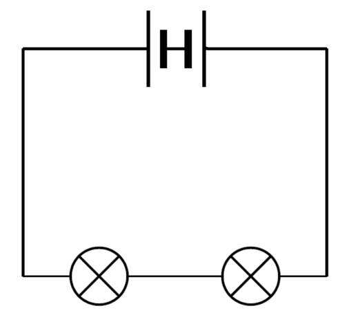
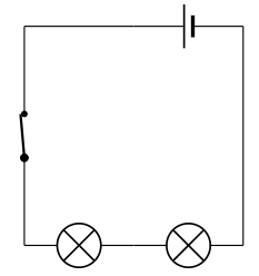
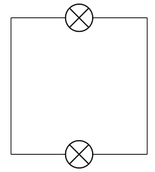
A closed circuit with one cell, two light bulbs and a switch.
An open circuit with two cells, two light bulbs and a switch.

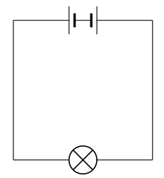
A closed circuit with 4 cells and one light bulb.
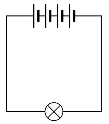
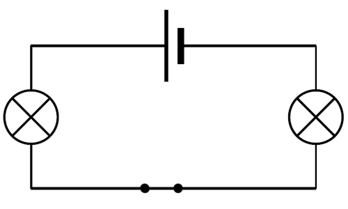
Look at the following circuit diagram. Identify the number of bulbs, switches and cells in this circuit.
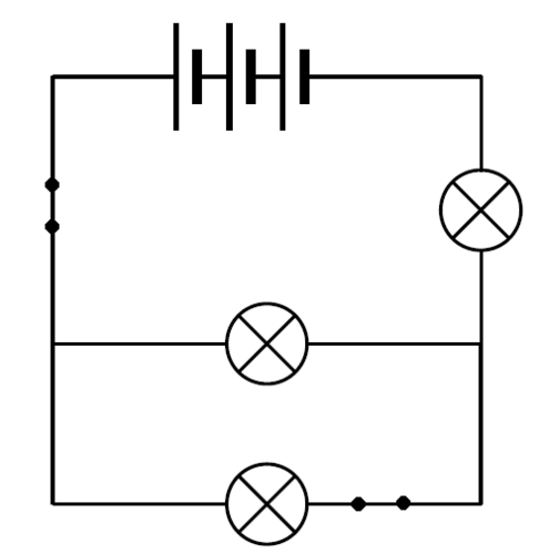
There are 3 cells, 3 bulbs and 2 switches.
What is wrong with the following circuit diagram? Does it represent a closed circuit? Explain your answer.
The one cell is in the wrong position as the two negative terminal are facing each other, instead of the negative terminal of one cell being connected to the positive terminal of the next cell.
Why do you think it is useful to have a switch in a circuit?
A switch provides an easy way of opening or closing the circuit and therefore controlling the electric circuit.
Why are conducting wires made out of metal?
This is because metals are good conductors of electricity.
Build you own electric circuits with this simulation. http://phet.colorado.edu/en/simulation/circuit-construction-kit-dc
Let's take a closer look at the source of energy in electric circuits.
All muscles in our bodies move in response to electrical impulses generated naturally in our bodies.
Electrical cells are the source of energy for the electric circuit. Where does that energy come from?
Inside the cell are a number of of chemicals. These chemicals store potential energy. When a cell is in a complete circuit, the chemicals react with each other. As a result, electrons are given the potential energy they need to start moving through the circuit. When the electrons move they have both potential and kinetic energy. The electric current is the movement of electrons through the conducting wires.
Cells come in many different sizes. Different sized cells provide different amounts of energy to the electrical circuit. The types of cells you would use in toys, torches and other small appliances range in size from AAA, AA, C, D, and 9-volt sizes. AAA, AA, C and D cells usually have a rating of 1,5V, but the larger cells have a larger capacity. This means that the larger cells will last longer before going 'flat'. A cell goes flat when it is no longer able to supply energy through its chemical reactions.
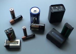
When we buy cells in the shop they are usually referred to as batteries. This can be a bit confusing because a battery is really two or more cells connected together. So when we refer to a battery in circuit diagrams we need to draw two or more cells connected together.
This activity is a good opportunity for both group work and individual work. The learners can do the research in a group but then write their paragraphs individually. Different learners in the same group may have different recycling centres closest to where they live. You can assess both the quality of their written response as well as the accuracy of their information.
Batteries which no longer work must not be thrown away in dustbins. They need to be recycled.
INSTRUCTIONS:
Find out why batteries should not be thrown away in normal dustbins. Write a paragraph to explain why.
Batteries contain toxic chemicals which can leak into the soil and contaminate the environment. Different batteries contain different substances. Lead-acid batteries, used in motor cars and other vehicles, are particularly damaging to the environment.
Find out where you can recycle batteries in your community. Write down the details of the centre(s) closest to where you live.
This answer will depend entirely on where the learner lives. Some areas will have little to no access to specialised collection points but most Pick 'n Pay, Spar and Woolworths stores now have battery recycling collection bins and there are various companies in the country which also offer this service. Most municipal dumps also recycle batteries separately.
A guide to recycling in South Africa. http://treevolution.co.za/guide-to-recycling-in-sa/
What are resistors? In order to work out what they are, let's first remind ourselves about conductors and insulators.
We are specifically looking at electricity so we can now talk about electrical conductors and insulators. An electrical conductor is a substance which allows electric charge to move through it. An insulator is a substance which does not allow electric charge to move through it.
Think back to our model of a metal wire and how the electrons are able to move through the wire. The metal wire is a conductor of electricity. Write down some materials which do not conduct electricity.
Some materials which do not conduct electricity are plastics, glass and ceramics.
Why do you think most conducting wires are surrounded with plastic?
This is because plastic is an electrical insulator and therefore insulates the wire.
Resistors are a bit of both. They allow electrons to move through them, but do not make it easy. They are said to resist the movement of electrons. Resistors therefore influence the electric current in a circuit.
Bring a kettle to school so that the learners can see the element inside the kettle. Also use a large, incandescent light bulb to show them the filament wire in the bulb as examples of resistors.
But, why would we want to resist the movement of electrons? Resistors can be extremely useful. Think about a kettle. If you look inside you will see a large metal coil.
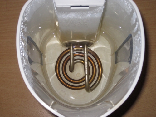
This metal coil is the heating element. If you plug in and switch on the kettle, the element heats up and heats the water. The element is a large resistor. When the electrons move through the resistor they expend a lot of energy in overcoming the resistance. This energy is transferred to the surroundings in the form of heat. This heat is useful to us as it heats our water.
The first electric light was made in 1800 by a man called Humphry Davy. He invented an electric battery, and when he connected wires to it and a piece of carbon, the carbon glowed as the carbon is a resistor, producing light.
The inventor, Thomas Edison, experimented with thousands of different resistor materials until he eventually found the right material so that the bulb would glow for over 1500 hours.
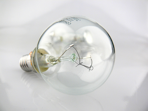
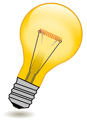
A good example of where resistors are used is in light bulbs. Let's take a closer look at the different parts of a light bulb to see how it works.
Try to have some incandescent light bulbs for the learners to hold and to look at. For extension you could ask the learners to research the use of argon gas rather than normal air for the gas inside the light bulb. Argon is used because it is an inert gas and will prevent oxidation of the filament, therefore lengthening the lifespan of the filament.
The questions in this activity would be discussed and answered as you go through it in class. Learners might not know the answers,but after discussing how a light bulb works with them, they should then write their own answers.
MATERIALS:
INSTRUCTIONS:
Incandescent means to emit light as a result of being heated.
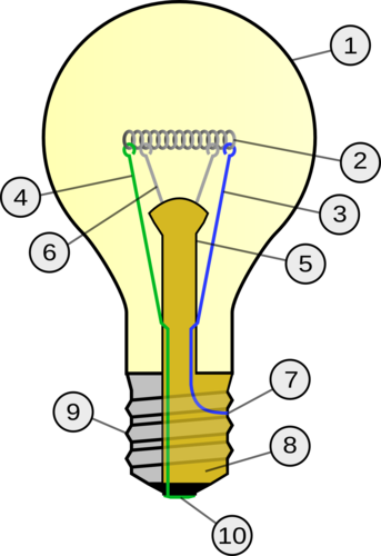
How a light bulb works.
A light bulb consists of an air-tight enclosed glass case (number 1). At the base of the bulb are two metal contacts (numbers 7 and 10), which connect to the ends of an electrical circuit. The metal contacts are attached to two stiff wires, (numbers 3 and 4).
These wires are attached to a thin metal filament. Have a look at a light bulb. Can you identify the filament? This is number 2 in the diagram. The filament is made from tungsten wire. This is an element with high resistance.
QUESTIONS:
When the electrons move through the filament they experience high resistance. This means that they transfer a lot of their energy to the filament when they pass through. The energy is transferred to the surroundings in the form of heat and bright light. Describe the transfer of energy in this light bulb.
Electrical energy is transferred to heat and light.
What is the useful energy output and what is the wasted energy output in this light bulb?
Light is the useful output and heat is the wasted output.
Can you see the filament is coiled? Why do you think this is so? Discuss this with your class and teacher.
NOTE: This is an extension question as learners will only cover factors affecting resistance later so discuss this as a class. This is to fit a longer length of tungsten within a small space to increase the resistance, and therefore brightness of the bulb.
The filament is mounted on a glass stem (number 5). There are two small support wires to hold the filament up (number 6). Why do you think the stem is made of glass?
Glass is an electrical insulator so it will not conduct electricity and all the current will pass through the filament.
The inside of the base of the bulb is made from an insulating material.This is the yellow part labeled number 8. On the outside of this is a metal conducting cap to which the wire is attached at number 7. Why is the wire attached at 7 making contact with the metal conducting cap?
This is so that the electrical current can pass in through the electrical contact at number 10 and then through to the wire at number 7, which is touching the inside of the metal insulating cap.
A fun game about electric circuits. http://www.andythelwell.com/blobz/guide.html
The link in the Visit box is an interactive tutorial and set of activities and quizzes to revise electric circuits and circuit diagrams.
If you want to revise some of the concepts from previous years, you can discover more online at[link]www.curious.org.za
The amount of resistance a substance offers to the circuit is measured in ohms (Ω). If we want to use resistors to control the current flow, then we need to know the amount of resistance. There are some common resistors shown in the photo.
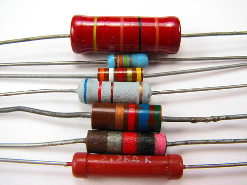
Can you see that there are different coloured bands on the resistors? This isn't just to make them look pleasing to the eye. The coloured bands are actually a code that tells us the resistance of the resistor. We also get resistors where we can adjust the resistance ourselves. This is called a variable resistor. You have already seen the symbol for drawing a resistor in a circuit diagram. Draw a circuit diagram in the space below with two bulbs, two cells, an open switch and a resistor.
Learner's diagram should look as follows:
An electric current can have various effects. Let's find out more about what these are.
We are going to look at the effects of an electric current, and specifically how we use these effects. An electric current can:
As electrons move through a resistor they encounter resistance and they transfer some of their energy to the resistor itself. We saw this in the last section where we looked at the filament in a light bulb and the element in a kettle.
A useful video on heat for extra, background information
This activity is to demonstrate that an electric current travelling through a resistor will cause the resistor's temperature to increase.
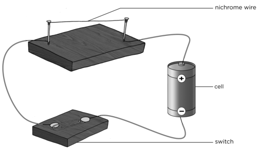
MATERIALS:
Nichrome wire can be bought at any hardware store. Do not leave the circuit on for too long. You want the learners to feel the warmth from the wire, not to burn themselves. This experiment can also be performed with the graphite from a pencil which will emit light as well as heat.
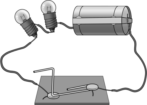
You can easily make your own switch by sticking two metal drawing pins into a piece of wood with a metal paper clip in between, as shown in the diagram.
INSTRUCTIONS:
Build the following circuit and keep the switch open.
Feel the nichrome wire. Is it hot or cold?
The wire should be cold
Feel the wire, briefly. Is it hot or cold?
The wire should be hotter than when they first touched it.
QUESTIONS:
Remember that heat and temperature are not the same thing. Temperature is a measure of how hot or cold something is (measured in °C) whereas heat is the transfer of thermal energy from a hotter object to a colder object (measured in J).
These questions can be used to assess whether learners have grasped the concept. They can be completed after the activity, or the next day in the following lesson as a revision of what was done, or as a homework task.
When you felt the nichrome wire after the circuit had been on for a while, you felt an increase in temperature in your skin as thermal energy, which was transferred from the wire to your skin. Explain the heating effect of the electric current in the resistance wire.
When the circuit is complete, there is a flow of charge (electric current). The electrons moving through the wire transferred energy to the wire in the form of heat. The particles in the wire therefore have more kinetic energy and so the temperature increases.
List 2 useful applications of the heating effect of an electric current.
Examples include: iron, kettle, heater, geyser, toaster.
Choose one of the applications you listed in question 2 and explain how the heating effect of the electric current is used.
Iron: The metal part of the iron has a high resistance and so it gets hot. This allows us to smooth out the creases in material.
Kettle: The element of the kettle has a high resistance and so it gets hot enough to boil the water.
Heater: The element in a heater has a very high resistance and so it gets very hot. The element heats the air around the heater.
Look at the following photo of a toaster.
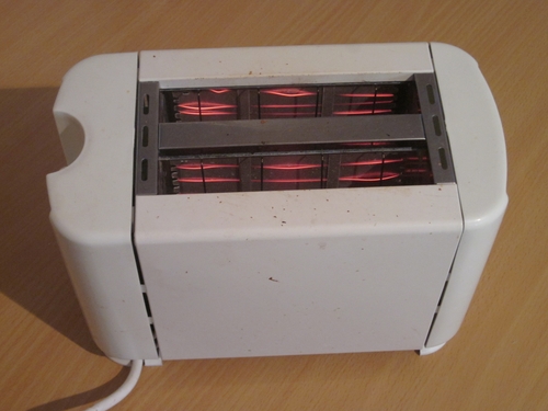
Can you see the glowing filament inside? Why does the element glow?
The electric current passes through the toaster and the element has a high resistance. Energy is transferred to the particles in the element so that they gain kinetic energy and the temperature of the wire increases. Some of the energy is also transferred as light to the surroundings and the wire glows.
So now we know that an electric current can cause objects to heat up. Let's look at a useful application of the heating effect.
Fuses are a practical application of the heating effect of an electric current. In this activity the learners will see that an electric current can melt a metal, not just warm it up. If you have enough equipment you could allow small groups of learners to complete this activity. Otherwise, use it as a demonstration.
MATERIALS:
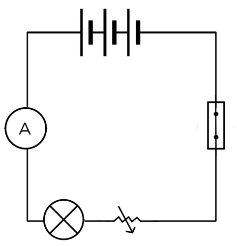
The light bulb is included to show that the current is flowing while the steel wool is in place but not flowing when the steel wool melts. The variable resistor is used to show that when the resistance is high, the current is low enough that the fuse warms up but doesn't melt. When the resistance is lowered, the current increases until it melts the steel wool.
If you are demonstrating and you want to make the activity more exciting then you can use a small ball of steel wool instead of a wire. This should make the steel wool spark and burn. This should be done behind a screen as the sparks could land on a learner.
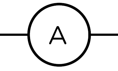
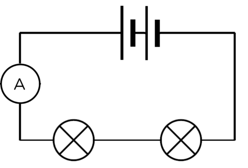
If you do not have a variable resistor then leave it out of the circuit and rather explain the concept. An ammeter is also not crucial in doing this activity as the light bulb can be used to indicate whether there is current or not.
An ammeter is used to measure the electric current in a circuit.
INSTRUCTIONS
Set up a circuit according to the following picture.
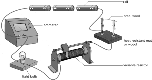
This must not be very thick. Just a few strands will do.
Close the switch. What do you observe?
The light bulb should glow and the steel wool should warm up but not melt.
Close the switch. What do you observe?
The steel wool melts/burns and breaks up and the light bulb stops glowing.
QUESTIONS:
Draw a circuit diagram for your circuit.
Why is the light bulb included in the circuit?
The light bulb is a good indicator of whether or not there is a current in the circuit. If the light bulb glows it means there is electric current. If the light does not glow it means that there is no current (or there is a very small current).
NOTE: Sometimes though there might still be a very small electric current, but it does not provide enough energy to cause the light bulb to glow. This is why the light bulb gives a good indication, but an ammeter will provide the most definitive indication of whether there is a current or not.
When you decreased the resistance, what happened to the current? In other words, what happened to the reading on the ammeter?
The current increases when the resistance decreased. The ammeter reading increases.
What do you think happens to the electric current when the steel wool has burnt? Explain your answer.
The current stops because the circuit has been broken. There is no longer a complete pathway for the electrons to move.
In this activity, we just demonstrated how a fuse works. The steel wool acted as a fuse. When the current was too high, the steel wool melted and prevented any further current in the circuit.
The heating effect of an electric current can be dangerous. If a circuit overheats it could cause a fire. To avoid overheating, circuits often contain a fuse. Fuses contain a low resistance wire made of a metal with a low melting point. Therefore, the piece of wire melt if it gets too hot, just like the steel wool in our activity.
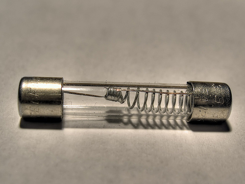
Different circuits need different strength currents and so we need different types of fuses. Some fuses can only handle a little bit of heat, some can handle a lot. We choose the fuse that suits the safety needs of our circuit. If the circuit overheats, the fuse will melt and break the circuit to reduce the danger of fire as well as protect electronic equipment.
How did you draw the fuse that we made using steel wool in the last activity? The conventional symbol for drawing a fuse in a circuit diagram is shown here:
It is important to never remove a fuse from a circuit without first switching off the current. You could get a nasty shock if you do.
Have you ever heard that something broke because it short circuited? A short circuit happens when another, easier path is accidently made in an electric circuit. What do we mean by easier?
We mean that the path offers very little resistance to the electric current. As there is so little resistance the current flows along the short circuit and doesn't pass through the main circuit. Short circuits can be dangerous and cause a lot of damage to appliances.
Have you ever had a piece of toast get stuck in a toaster? It's a real nuisance. Lots of people are tempted to use their butter knife to unhook the bread. Don't be tempted. Your knife is a conductor and can act as a short circuit. All the electric current will flow through your knife and, because you are touching it, through you. What would be the safe way to unhook your toast?
Either switch off the toaster and then unhook the toast (safest idea!) or use an insulator (plastic) utensil to unhook the toast.
This activity is an opportunity for individual research. There will be other opportunities for group research. It is important that each learner is able to do basic research so that they are able to contribute effectively to a group research task. The learner should write a short paragraph detailing their research. There are many different household appliances which use fuses. Learners may choose any of them. Remember to make sure that all learners include references for any research they do. They need to learn from an early age to credit sources of information.
INSTRUCTIONS:
This answer will depend on the appliance chosen. Ensure that the paragraph doesn't only describe the appliance but also explains why the fuse is necessary to prevent accidents.
There are different types of fuses. The ones we have investigated so far require you to replace the fuse if the wire melts. However, some fuses work differently to break the circuit and can just be reset once the problem in the circuit is fixed.
Most modern homes have circuit breakers instead of fuses. A circuit breaker is similar to a fuse in that it is designed to protect an electric circuit from damage, due to overload or a short circuit, by stopping the current flow. However, unlike a fuse which melts and must then be replaced, a circuit breaker can be reset to start operating again. This can be done manually or take place automatically.
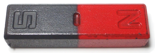
Before we look at how a current produces a magnetic field, let us first learn more about magnets. A magnet is a piece of material which produces a magnetic field. A magnet has a north pole and a south pole. Opposite poles will attract each other and the same poles will repel each other. A magnet has a magnetic field around it.
Some fun tricks with magnets. (video)
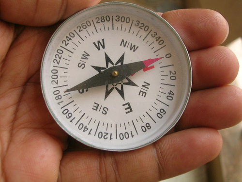
Did you know that the Earth is like a bar magnet with a North and a South Pole? The Earth has a magnetic field. This is why we can use compasses to tell direction. A plotting compass has a needle with a small magnet. The needle points to magnetic north because the small magnet is attracted to the opposite magnetic pole and can be used to determine direction.

What is the magnetic field?
This activity allows the learners to see that a plotting compass will respond to a magnetic field. It will allow them to visualise the lines of the magnetic field around a bar magnet. Once the learners are convinced that the plotting compass can model a magnetic field, you can use the compasses to show them that there is a magnetic field around a current-carrying conductor.
MATERIALS:
INSTRUCTIONS:
Hold the plotting compass in your hand. The north end of the needle should point to magnetic north.
Put the bar magnet flat on the desk. Make sure you know which end is north and which is south. If you are not sure, ask your teacher.
Put plotting compasses in a circle around the bar magnet. Draw what you see.
Do not assess drawing skills but make sure that the drawing clearly shows that the plotting compass needles have "lined" up and make a discernable pattern. It is not necessary at this stage to explain the pattern. It is just important that the learners realise that a plotting compass will respond to a magnetic field.
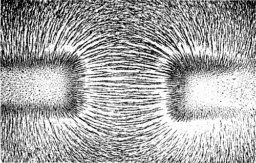
Next, place a white sheet of paper over the bar magnet and sprinkle iron filings over the sheet of paper over the magnet.
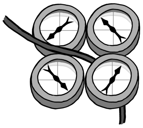
Observe what happens to the iron filings. Did you see something similar to what is shown in the photograph below? Describe what you see.
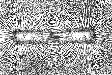
Learners should describe how they see the iron filings clump together into long lines indicating the magnetic field at each point.
As an extension to indicate to learners how two like poles repel each other, but two opposite poles attract each other, place two bar magnets on a surface with two like poles facing each other and sprinkle iron filings over the piece of paper. You should observe something similar to the photo below.
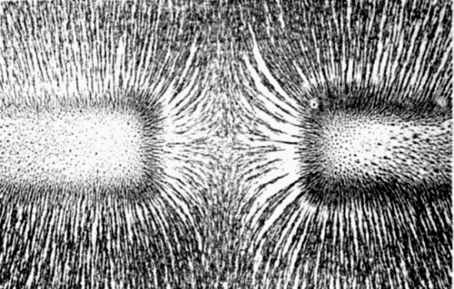
Next, turn one magnet around so that opposite poles are now facing each other and sprinkle the filings over the paper again. You should observe a pattern similar to the photo below.
Explore the interactions between a compass and bar magnet with this simulation. http://phet.colorado.edu/en/simulation/magnet-and-compass
So now we know that there is a magnetic field around a magnet and that plotting compasses and iron filings can be used to visualise that field. Is there anything else that has a magnetic field around it?
This activity will show the learners that the plotting compasses align with a magnetic field around a current-carrying conductor. It is important to make sure that the learners realise that it is a 3D magnetic field and that it surrounds the conducting wire. Learners often assume that the magnetic field only exists where the plotting compasses are placed.
MATERIALS:
INSTRUCTIONS:
Put the plotting compasses on either side of the conducting wire as shown in the diagram, as well as below and above the conducting wire.

Keep the switch open. What do you notice about the needles of the plotting compasses?
The needles should point to magnetic north.
The drawing does not need to be assessed according to the learners drawing skills. What is important is that they see that the compass needles are aligned in a circle when the switch is closed.

What does the pattern of the compasses tell us?
That there is a magnetic field around the wire.
We saw from our first activity that plotting compasses react to magnetic fields. The plotting compasses changed direction when the current was switched on. This means there is a magnetic field around the wire. Was it there when the current was switched off? No, it was not. That means that the presence of the electric current in the wire must have produced a magnetic field.
Discover how the Earth is a magnet that protects us from damaging radiation from the sun!
The magnetic effect of an electric current has many useful applications.
How to make an electromagnet (video)
If the learners' electromagnets are not strong enough to pick up the paperclips, suggest they use more batteries or add more coils of wire to the nail. Make sure that their coils are tightly packed, all in the same direction and do not overlap anywhere.
MATERIALS:
INSTRUCTIONS:
Iron filings can be bought

QUESTIONS:
What happened when you held the nail over the paper clips?
The paper clips should be attracted to the nail.
Why were the paper clips attracted to the nail?
The electrical current in the coiled wire caused a magnetic field to form. The magnetic field attracted the metal in the paper clips.
Did the disconnected nail attract the paper clips? Why?
The disconnected nail didn't attract the paper clips because there was no current in the wire and so there was no magnetic field.
Discover how you can use a battery and wire to make a magnet with this simulation. http://phet.colorado.edu/en/simulation/magnets-and-electromagnets
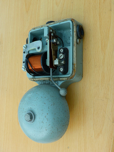
Electromagnets can be used in all sorts of practical applications, including speaker and electric bells, as you can see in the photo.
Electromagnets in a speaker. http://electronics.howstuffworks.com/speaker5.htm
Assign different applications to different groups so that you cover a range in the class.
INSTRUCTIONS:
Here is a general description of each application.
Speakers:
The voice coil of a speaker is an electromagnet. The power to the electromagnet is switched on and off in the same sequence as the incoming sound wave signal. This causes the magnetic field to switch on and off. When the magnetic field switches on and off the electromagnet moves backwards and forwards. This movement moves the diaphragm of the speaker and causes the air in front of the speaker to vibrate, causing a sound wave.
Electric bells:
The electric bell uses an electromagnet to move the striker backwards and forwards onto the bell itself. As the striker hits the bell the circuit is broken and the electromagnet switches off, a spring pulls the striker back into position, completing the circuit. When the circuit is complete the electromagnet switches back on and is attracted to the other magnet on the bell. The striker is then pulled to the bell. This process is completed until the bell is switched off.
Telephones:
The input sound from the person speaking is converted into an electrical signal which travels to the listener's device. The electrical signal has the same fluctuations and frequency as the speaker's voice. This current flows through a solenoid and causes an electromagnet to switch on and off. This causes the diaphragm to move in and out which causes a sound wave.
Magnetic trains (MAGLEV):
MAGLEV trains use the fact that magnets repel each other to power the trains. There are magnets on the track and on the bottom of the train. By alternating the current in the rails the train can be pulled forward by attraction between unlike poles and propelled forward by the repulsion of like poles. This website provides a good description: http://science.howstuffworks.com/transport/engines-equipment/maglev-train.htm
Industrial lifters and separators :
Electromagnets can be used to separate ferromagnetic materials from non-magnetic materials. When the electromagnets are switched on they attract the magnetic materials but leave the non-magnetic materials behind. When the electromagnet is switched off, it releases the magnetic materials.
Discover how to generate electricity using bar magnets with this simulation. http://phet.colorado.edu/en/simulation/generator
How to build a simple electric motor.
The last effect of an electric current that we are going to look at is how an electric current can cause a chemical reaction in a solution.
This activity will demonstrate the chemical effect of electricity. There is no need to explain the mechanism of the chemical reactions which occur. You might have already done this as a demonstration in Matter and Materials in Chapter 1 (Atoms). If you want to revise what you did then, you can explain why copper forms on the negative electrode and chlorine gas forms at the positive electrode.
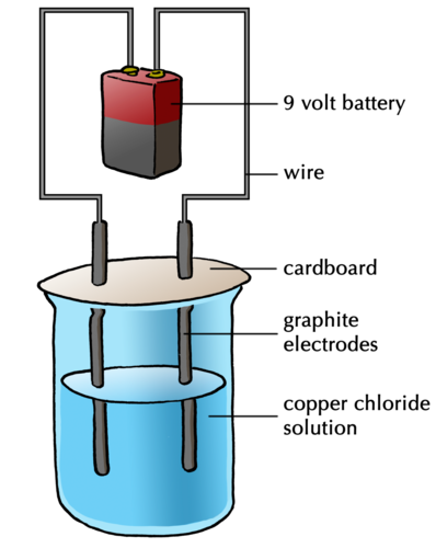
You might already have done this activity in Matter and Materials when we investigated the decomposition of copper chloride. We are going to perform it again, this time focussing on the effects of an electric current.
MATERIALS
If you don't have carbon electrodes then you can strip the wood from an HB pencil. Do this carefully so that the carbon rod in the centre doesn't break. You don't have to strip all the wood off the pencil. Strip off some from the bottom to allow it to make contact with the copper sulphate solution and enough wood off the top to allow the crocodile clip to grip the carbon. The pencil carbon is not pure and so won't work quite as effectively as pure carbon electrodes.
To make a copper chloride solution, dissolve 15 g of copper chloride in 100 ml of warm water.
This torch bulb is not strictly necessary. It is just to show that there is a current in the circuit and that there is still a complete pathway.
INSTRUCTIONS
Look at the electrodes. What do you observe?
Nothing is happening at either electrode. This is because the current is not flowing.
Turn on the power source. Leave it on for a few minutes.
QUESTIONS
When you switch on the power source, does the torch bulb glow?
Yes.
NOTE: If the torch bulb does not glow then there is no current in the circuit. Make sure that the electrodes are not touching each other and neither are the crocodile clips. The crocodile clips must not be touching the solution either.
What do you observe happening at the two different electrodes?
One of the electrodes should be developing a layer of copper and there should be bubbles developing at the other electrode.
Can you smell anything? What do you think this is?
Learners should be able to smell the chlorine gas.
What is happening to the copper chloride solution when the electric current is passed through it?
The copper chloride solution is being chemically separated into pure, solid copper and chlorine gas.
If you switch off the power source, what happens?
Bubbles are no longer forming at the electrode because the reaction has stopped.
What is causing the separation of the copper chloride?
The electric current is separating the copper chloride.
Why is it important that you do not let the carbon electrodes touch each other while the current is flowing?
It would cause a short circuit. The electrical current will then not move through the copper chloride and no separation will occur.
The separation of the copper chloride means that an electric current can cause chemical reactions to occur. There are many ways in which we can harness this chemical effect for practical uses.
Electrolysis is the breaking down of a substance into its component elements by passing an electric current through a liquid or solution. We can also use electrolysis to purify substances.
Impure copper can be purified using electrolysis. Instead of using carbon electrodes in a copper sulphate solution we can use copper electrodes. If one of the copper electrodes is pure copper and the other is impure copper, then the impure electrode will break down and deposit pure copper on to the already pure copper electrode.
Silver refining through electrolysis.
One of the most important uses of electrolysis is electroplating.
Electrolysis is used to electroplate metals. In the last activity, one of the carbon electrodes was coated with an even layer of pure copper. We say that the carbon electrode was electroplated with copper.
Why do we electroplate? An example is in the making of jewellery where an inexpensive metal is made into a ring, for example, and then coated with gold by electroplating. This makes it less expensive than if it were made from pure gold. Iron rusts easily and so it is useful to coat it with a layer of a zinc to protect it from corrosion. Many car parts, bathroom taps and wheel rims are electroplated with chromium.
The process of electroplating (video)
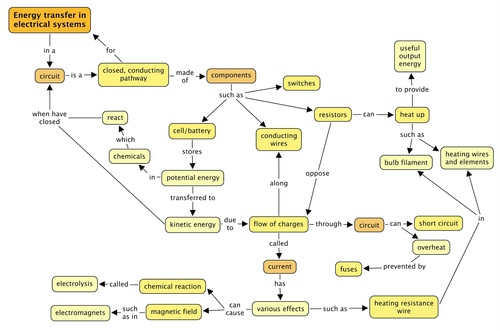
Concept map
Complete the concept map to summarise what you have learned about electric circuits and the effects of an electric current in this chapter.

Teacher's version:
Write your own definition for an electric circuit. [2 marks]
An electric circuit is a closed, complete electric pathway or system for transferring electrical energy.
What type of energy does a battery have? [1 mark]
It has potential energy.
When a battery is connected to a circuit, it causes an electric current in the circuit. Explain what an electric current is and why it is possible in metals. Use the word 'delocalised' in your explanation. [3 marks]
An electric current is the movement of charge/electrons. It is possible in metals as the electrons are delocalised, meaning they are not associated with an atom and are free to move through the wire.
List 3 materials which conduct electricity. [3 marks]
There are many different materials which conduct electricity, any 3 can be listed, such as various metals.
List 3 materials that do not conduct electricity. [3 marks]
There are many different materials which are insulators, any 3 can be listed, such as plastics, glass, ceramics.
You have a battery, insulated copper conducting wires and a light bulb. Draw a setup which would allow you to test whether the materials you listed in questions 1 and 2 are conductors or not. [4 marks]
This diagram should have the components connected in series with each other. There should be a gap in the circuit which can be filled by the different materials to be tested. A possible diagram is given here:
A cell | A light bulb |
A conducting wire | An open switch |
A resistor | A variable resistor |
A cell  | A light bulb  |
A conducting wire  | An open switch  |
A resistor  | A variable resistor  |
Circuit | Glow/Not Glow | Explanation |
 | ||
 | ||
 | ||
 | ||
 |
Circuit | Glow/Not Glow | Explanation |
 | Will not glow. | The switch is open so the circuit is broken. |
 | Will glow. | The switch is closed and there is a complete circuit. |
 | Will not glow. | There is a closed circuit but the two negative terminals of the cells are connected, rather than a negative connected to a positive terminal. |
 | Will glow. | There is a complete circuit with an energy source. |
 | Will not glow. | There is a complete circuit but no energy source. |
Which of the following setups shows the correct way to connect a light bulb to a battery? Explain your answer. [2 marks]
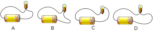
Setup B is the correct connection as there is one electrical contact point in the tip of the bulb and the other point of contact is the metal casing.
Image | Circuit diagram |
 |
Image | Circuit diagram |
 |  |
An electrician wants to replace a faulty fuse with a normal piece of conducting wire. Should you let him? Why or why not? [3 marks]
A fuse is a safety device to prevent overheating in the circuit. A normal wire would not melt if overheated and so would not prevent damage or fires. You should not let him.
A child, while inserting an electric plug into the socket, did not see that there was a thin piece of aluminium foil stuck between the pins of the plug. When he turned the switch on, he noticed a spark at the plug, and at the same time, the lights went out. What could have happened to cause the spark and to make the lights go out? [4 marks]
The aluminium foil can conduct electricity. This means that a short circuit has been created. The short circuit caused a large current which would have melted a fuse and broken the electric circuit. This would have caused the electricity to switch off.
What is the benefit of using a circuit breaker rather than a fuse? [2 marks]
A circuit breaker is advantageous to use over a fuse as a fuse needs to be replaced once the metal wire melts, whereas a circuit breaker automatically detects the fault in the circuit, breaks it, and can then be reset to start operating again, either manually or automatically once the fault has been repaired.
Look at the following photo of a light bulb. Label the filament and explain why it glows. [4 marks]
NOTE: 1 mark is for labeling the filament and 3 marks for the explanation.
When an electric current passes through the tungsten filament, it experiences resistance as the tungsten has a high resistance. The tungsten wire therefore heats up as energy is transferred from the moving electrons to the wire. The wire heats up and also emits light.
You place some plotting compasses around an electric wire and observe the following.
Is there are current in the conducting wire? [1 mark]
Explain your answer. [2 marks]
Yes, there is.
We know this because when there is current in an electric wire, it generates a magnetic field around it. The plotting compasses respond to the magnetic field as the arrows are all pointing around in a circle and not all the same way as they would do if there was no current.
Give two advantages of electroplating iron metal. [2 marks]
To prevent corrosion and enhance its value.
Total [55 marks]