Bevel gears, bicycles and systems diagrams
In this chapter, you will learn how to draw bevel gears. We usually draw bevel gears from the side to show how the driver gear changes the direction of the driven gear. Then you will look at the gears on a bicycle. You will analyse which gears give a speed advantage, and which gears give a mechanical advantage.
Then you will use the systems approach to draw gear systems and show how an input speed is changed by a gear system into a different output speed.
Sketching bevel gears
Do you remember learning about bevel gears in Chapter 1? You learnt how bevel gears were used on a hand drill. Bevel gears are used when we want to change the direction of turning.
Look at Figure 2. It shows how you would draw two bevel gears of equal size.
When you turn the driver gear at the bottom, the driven gear rotates at the same speed. But the direction of rotation is turned through 90°.
Direction of rotation means the direction that a gear rotates or moves in.
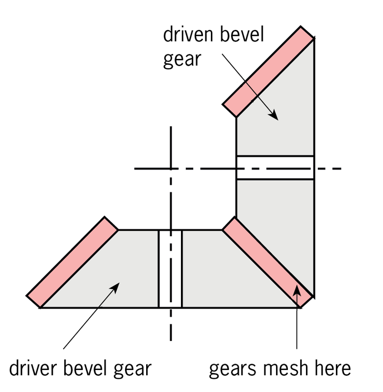
1. Make a sketch of the system shown in Figure 2 in the space below.

Changing the speed of a bevel gear
The driver gear and the driven gear of a bevel gear system do not have to be the same size.
If the driver gear has a pitch diameter of 50 mm and the driven gear has a pitch diameter of 100 m, the driven gear will turn slower than the driver gear. This system will give you a mechanical advantage.
Study Figure 3 and then answer the following questions:
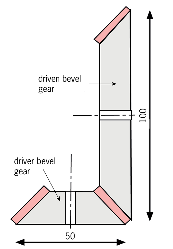
1. Make a sketch of the system shownin Figure 3 in the space below.
Sketch a bevel gearbox system
Figure 4 shows a speed-reducing gearbox that gives a mechanical force advantage. This gear system has a straight gear system and a bevel gear system.
1. Make a 2D sketch of this systemin the space below. Draw thestraight gears as rectangles andthe bevel gears like those shownin Figure 4.
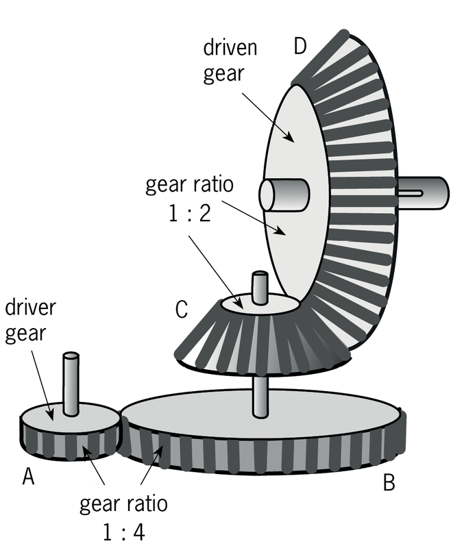

2. What is the mechanical advantage between the driver gear A and gear B?
3. What is the mechanical advantage between gear C and the driven gear D?
4. Calculate the total mechanical force advantage between the driver gear and the final driven gear.
Chain drives
In this activity, you will investigate the gears on a bicycle. You will learn about chain drives and how they are like gear systems that have an idler gear.
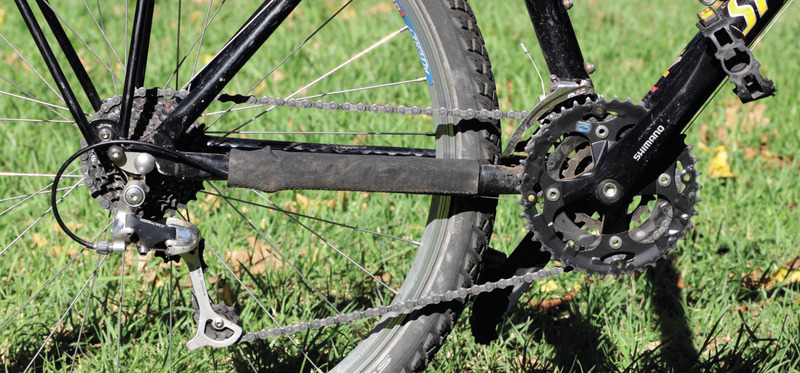
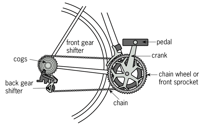
Look at Figure 5. It shows the gear system on a modern bicycle.
When you ride a bicycle, you pedal. The pedals push the cranks up and down. The cranks force the chain wheel to turn.
Attached to the chain wheel is the chain. When a cyclist pedals, the chain is pulled around in a clockwise direction.
The chain meshes with the gears on the cogs, which are attached to the back wheel. The gears make the back wheel turn and the bike move forwards.
Questions
1. What do you call the large gear wheels at the front that are turned by the pedals?
2. What do you call the group of gears that turn the back wheel?
3. What connects the front gears to the back gears?
4. What do you call the mechanism that changes the gears?
Investigating the chain drive of a bicycle
Bring a bicycle with gears into your classroom. Turn it upside down so that you can investigate how the gears work. Stick a piece of tape somewhere on the wheel. This will help you to count how far the wheel rotates for each pedal rotation.
Use the front gear shifter to put the chain onto the smallest gear of the chain wheel. Use the back gear shifter to put the chain on the biggest cog at the back.
1. Count the number of teeth on the smallest gear of the chain wheel and write it down.
2. Use the back-gear shifter to put the chain onto the largest cog on the back wheel. Now count the number of teeth on this gear and write it down.
3. If you rotate the crank by exactly one revolution, how many revolutions does the wheel make?
4. Will this gear position give you a speed advantage? Explain why you say so.
Advantages of using a chain drive rather than spur gears
- Chain drives can easily and cheaply connect gears that are far away from each other.
- A chain can be adjusted easily if the distance between the axles of the two gears changes.
- With spur gears, the axles need to be aligned precisely, so that the gears mesh well but without too much resistance. With a chain drive, the axles do not have to be aligned precisely because the chain can bend sideways a little.
. 3 gear systems diagrams
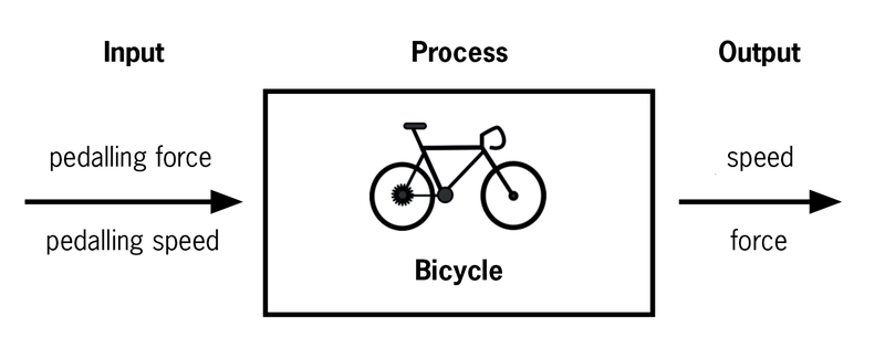
Sometimes a diagram of a mechanical system can be very complicated. Systems diagrams are simpler diagrams. A systems diagram does not explain how the system works. Rather, a systems diagram describes the input, process and output of a system. Have a look at Figure 6 below. It is a systems diagram for a bicycle.
Input, process, output
Have another look at Figure 6 and read the information below. It tells you how this systems diagram for a bicycle works.
On the left, there is the input to the bicycle. The input is what you put into a bicycle when you ride it. It is the pedalling force and the pedalling speed. In the process box in the middle is the bicycle.
The chain drive of the bicycle changes the input pedalling force and pedalling speed into an output. On the right is the output. This is what you get out of a bicycle, which is speed.
A system diagram shows how a system will change inputs into outputs. The process changes the inputs into outputs.
When you change the pedalling force or the pedalling speed on a bicycle, the output speed will change. The systems diagram will help you to work out how these will change.
Draw systems diagrams of gears and drives
You can use systems diagrams to represent gear systems instead of drawing them. Look at the systems diagram in Figure 7. It shows a belt drive system for a car's alternator.
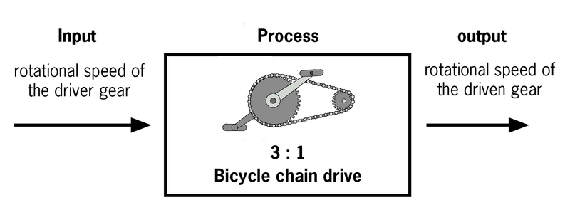
The system in Figure 7 gives a speed advantage of 3. You can use the diagram to work out what the output speed will be if the input speed should change.
If the input speed from the car's engine on the driver side is 500 rpm, then the alternator speed will be 1 500 rpm.
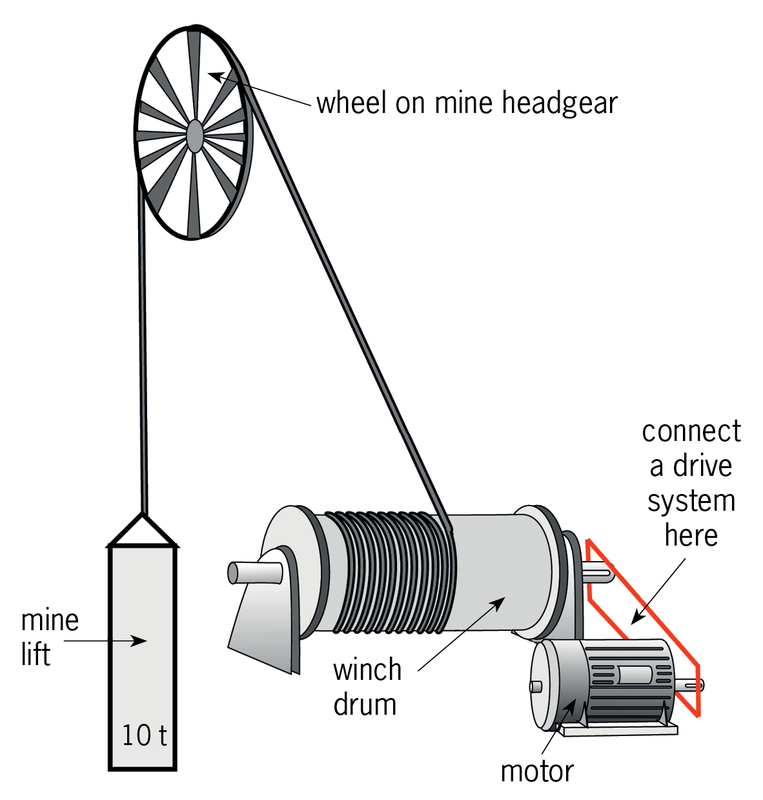
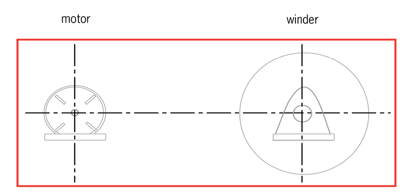
A winch for a mine
A winch is used for a lift in a mine. The winch consists of an electrical motor and a winch drum on which cable is wound.
The winch must be able to lift 10 000 kg of mined rock. If the motor is connected directly to the winch drum, without a gear system, the winch can lift a maximum of 2 000 kg.
1. Calculate the mechanical advantage needed from a gear or chain-drive system to enable the winch to lift the load of mined rock.
2. Sketch a drive system in the box below to show how the motor will make the winch turn. You do not have to sketch it to scale.
Next week
Next week, you will research a topic about the impact of mining on people and the environment, and give a presentation on that topic. Your teacher will divide you into teams today, and give each team a topic. There will not be a lot of time next week to prepare for your presentation, so it is very important that you start your preparation now. Read the article on your team's topic in Chapter 5 during the weekend.