Tools with two or more levers
In this chapter, you will learn how levers are combined to make different tools.
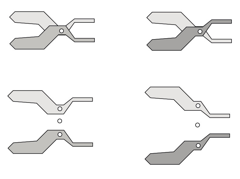
Figure 1 : A set of pliers consists of two levers attached at the same pivot point.
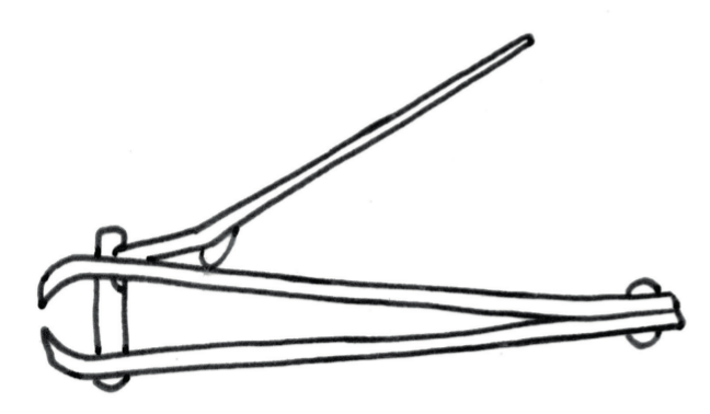
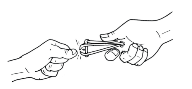 Figure 3
Pairs of first-class levers
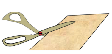
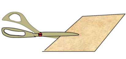
Work with scissors in different ways
First answer the questions below and then do the experiment. Find out which way or method of using scissors works the best. Look at the two methods of using scissors in the pictures below.
-
What is the difference between these two methods of using scissors?
-
With which method will it be the easiest to cut? Explain your answer.
-
Are there any levers in a pair of scissors? If so, how many, and what kind of levers are they?
-
In diagrams A, B and C below, the input force on the blue blade is indicated with a red arrow in each instance. In diagram A the load on the blue blade is indicated by a black arrow.
-
Draw an arrow to show where the load is in diagrams B and C.
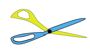
Figure 6: A pair of scissors is actually two blades that are linked together so that they work like two levers.
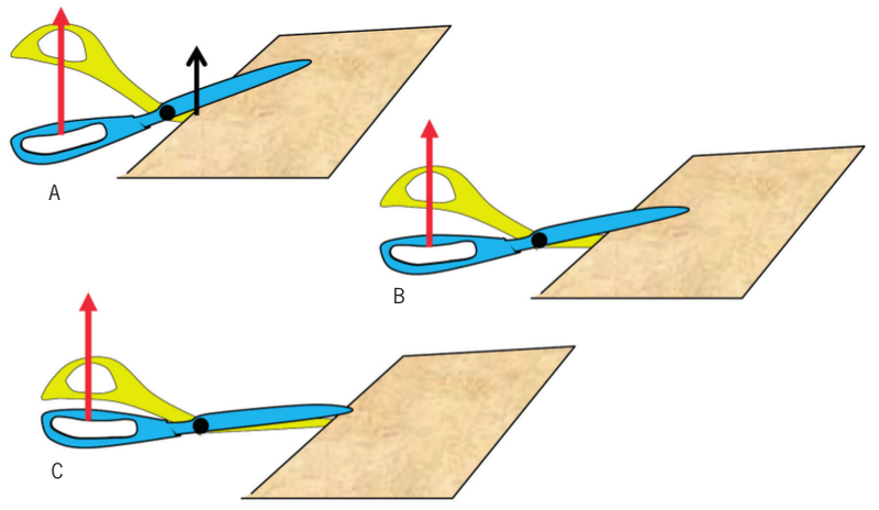
Figure 7 -
-
In which case is the mechanical advantage of the blue lever the greatest, and in which case is it the smallest?
-
In which case, or cases, is the mechanical advantage of the blue lever bigger than 1?
Can scissors cut thick objects?
-
Why will an ordinary pair of scissors not work well to cut the branches of a tree?
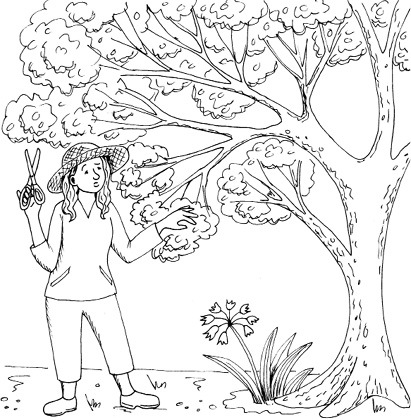
Figure 8
-
Make a free-hand sketch of the type of scissors that can cut the branches of trees. Why will it work?

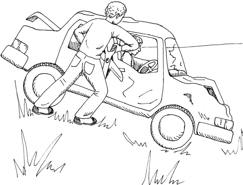
Figure 9
-
Why will an ordinary pair of scissors not work well to cut a crashed car open to free trapped passengers?
-
Suppose you have to design a cutting tool that can be used to cut through metal. In which ways will this tool be different from an ordinary pair of scissors?

More tools with levers
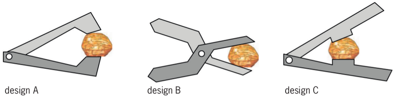
What is the best way to crack a nut?
You can use pairs of levers to compress, crush or crack things.
-
Which class of lever is used in each of these nutcrackers?
-
Quickly draw a hand in each case below to show how you can press the hardest on the nut.
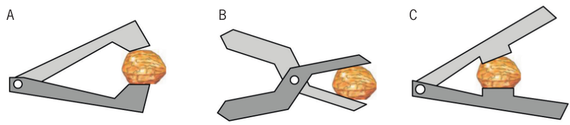
Figure 11 -
Mark and label the input force, load and fulcrum clearly on each of the above drawings.
-
Which of the three nutcrackers do you think will work best? Explain why you think so.
A label is a word or sentence that you write next to a drawing to describe or to name a part of the drawing. When you write one, you are labelling a drawing.
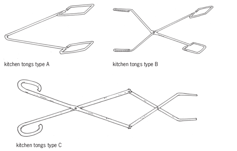
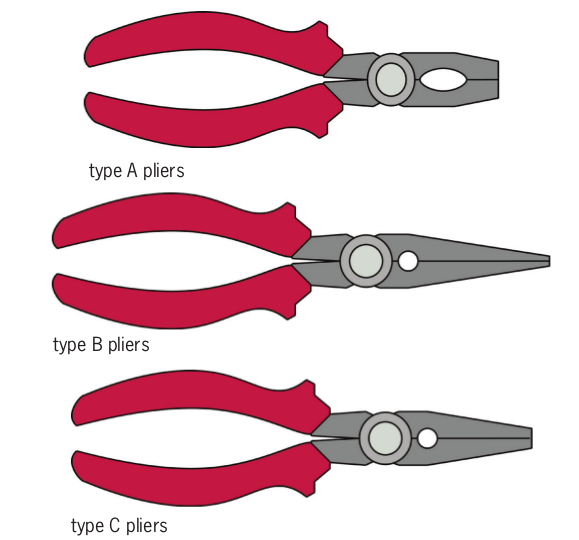
Three different kinds of kitchen tongs and two pairs of pliers are shown on the next page.
-
Describe the differences between type A and type B kitchen tongs.
-
How does type C kitchen tongs differ from types A and B?
-
Which of the three types of kitchen tongs work in the same way as a pair of pliers? Explain your answer.
-
Describe a situation in which a pair of pliers would be useful.
-
Make a free-hand drawing of a pair of levers that can be used to pull out thorns from your foot. This tool is called a pair of tweezers.
-
Which class of lever did you choose for your design in question 9?
-
Make a free-hand drawing of tweezers with a different class of lever than the tweezers in your first design.
Many levers in one device
Examine and redesign a nail clipper
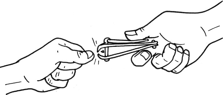
Figure 14
A bigger drawing of the nail clipper on its own is shown below, and a schematic diagram of a nail clipper is shown on the next page.
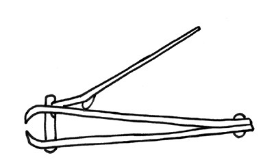
Figure 15
A schematic diagram does not show an object as it really looks. It is drawn to show some parts of the object more clearly than if you were looking at the real object.
-
Look at the red part on the diagram on the next page. It is a lever. What class of lever is it when the nail clipper is used?
-
Show the effort and load on the red lever with arrows and labels. Also show the pivot point with a small triangle and a label.
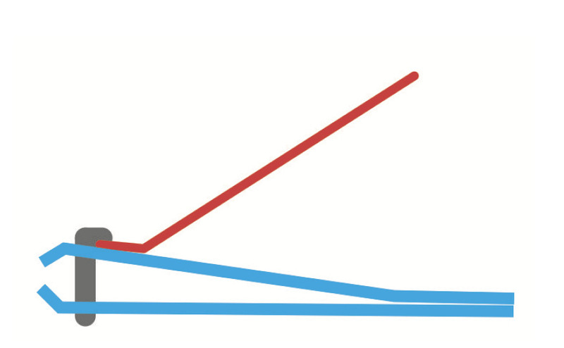
Figure 16
-
The blue part of the nail clipper is a pair of levers. Are they used as first-class, second-class or third-class levers?
-
Show the effort and load on one of the blue levers with arrows and labels. Also show the pivot point with a small triangle and a label.
-
Is the effort on the lower blue lever the same as the load on the red lever or not? Explain your answer.
-
Can the above design be changed so that the nail clipper could cut harder objects than finger nails, for example pieces of metal? Make a schematic drawing to show how that could be done and explain why it will have a greater mechanical advantage than the design above.

Investigate another combination of levers
The red and blue mechanism consists of two pairs of first-class levers. The pair on the left is used to "drive" the pair on the right.
The four yellow dots show linkages, like the linkages you made with paper dowels when you made levers in the previous two chapters.
Something that is designed to be useful when some of its parts move is called a mechanism.
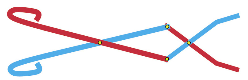
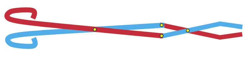
Figure 17
-
What do you think is the purpose of this device?
-
Which of the yellow linkages in the drawing are pivots for levers, and which only connect one lever to another? Show this by writing labels on the drawings above.
The word system is used to describe something that consists of several parts that are connected to each other in some way.
The above device can also be described as a system of two pairs of first-class levers.
Next week
In the next chapter, you will design a tool to cut open car wrecks, in order to save people trapped in crashed cars.